


- 6 -
Uscita cavi
Cable exit
Sortie des càbles
Kabelausgang
Salida cables
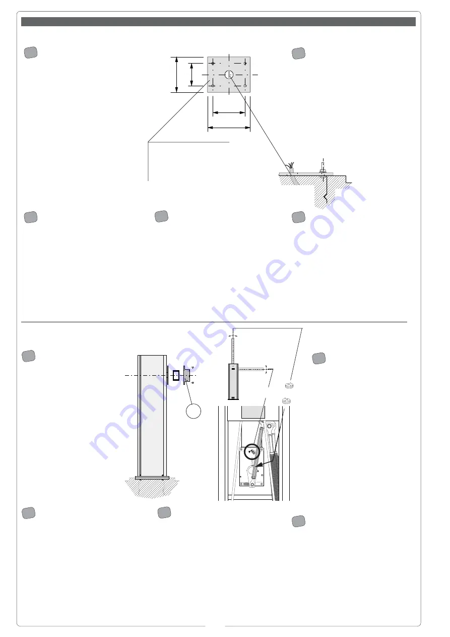
Montaggio -
Installation - Montage - Montage - Montaje
2) - Procedere alla posa
del gruppo: è consigliabile
sistemare l'armadio con lo
sportello ispezionabile vista
interna (vedi pag. 8).
Montare l'asta calcolando la
giusta lunghezza e fissare il
rispettivo attacco porta-asta A
tramite le quattro viti in dotazio-
ne.
Registrare la linearità verticale
ed orizzontale dell'asta agendo
sul fermo meccanico B e sulla
leva di trasmissione C.
2) - Place the unit on the
concrete base: it is good practice
to install the case so that the
access door can be opened from
the interior of the installation site
(see on page 8).
Mount the barrier as follows: first,
determine the length of barrier
required. Then, mount the barrier
holder with the four screws
provided.
Regulated mechanical stop B and
transmission arm C to adjust the
barrier rod for linearity in the
vertical and horizontal positions.
2) - Procéder ensuite à la pose du
groupe: il est conseillé de placer
l'armoire avec la porte de contrôle vue
intérieure (voir p. 8).
Monter la lisse en calculant la longueur
exacte, puis fixer le support de la barre
correspondante en utilisant les quatre
vis fournies avec l'appareillage.
Régler la linéarité verticale et
horizontale de la lisse en agissant sur
l'arrêt mécanique B et sur le levier de
transmission C.
2) - Gruppe aufstellen: Der
Schrank sollte mit Abdeckplatte zur
Innenseite aufgestellt werden (siehe
Seite 8).
Nach Berechnung der Stangenlänge,
Stange montieren und Stangenhalter
mittels der vier mitgelieferten Schrau-
ben festschrauben.
Die vertikale und horizontale Linearität
des Schrankenbaums durch Einwirken
auf die mechanischen
Festellvorrichtungen B und den
Antriebshebel C einstellen.
2) - Colocar el grupo: se reco-
mienda colocar el armario con el
portillo inspeccionable visto desde
el interior (ver pág. 8).
Montar la barra calculando la longitud
correcta y fijar el porta-barra relativo
mediante los cuatro tornillos del
equipo.
Regular el alineado vertical y horizontal
del hasta actuando en el tope
mecánico B y en la palanca de
transmisión C.
I
GB
F
D
E
1) - Predisponer, en función de las
medidas del grupo, una plataforma de
cemento introduciendo las grapas de
anclaje y la base relativa que consien-
ten fijar el grupo.
La base de fijación debe estar total-
mente horizontal, con los extremos
limpios y la rosca de los tornillos en
superficie.
De la misma deben sobresalir los
cables para las conexiones eléctricas.
1) - Pour a concrete base of the
correct size for installation of the unit.
When pouring, sink the anchoring stays
and the mounting base for the unit into
the concrete.
The concrete base must be perfectly
level and clean from end to end. All
screw threads must be completely
accessible from the surface of the
concrete base.
The electrical cables for the unit must
also protrude from the base.
1) - En tenant compte des
dimensions du groupe, préparer une
plate-forme en ciment dans laquelle
seront noyés les étriers d'ancrage et la
base correspondante qui permettront
de fixer le groupe.
La base de fixation devra être parfaite-
ment de niveau et propre sur toute sa
surface.
Le cables pour le branchement
électrique devront sortir de cette base.
1) - Ein den Abmessungen der
Gruppe entsprechendes Fundament
zum Einbetonieren der an der
Ankerplatte angebrachten
Fundamentanker, die der Befestigung
der Gruppe dienen, vorbereiten.
Die Befestigungsplatte muß eben,
sauber und livelliert sein und die
Ankerschraubengewinde müssen
volkommen frei über der
Fundamentebene liegen.
Die Stromversorgungskabel müssen
aus dem Fundament herausragen.
1) - Predisporre,
dimensionandola in base alle misure
del gruppo, una piazzola di cemento
con annegate le zanche di ancoraggio
e la relativa base che permetteranno il
fissaggio del gruppo.
La base di fissaggio dovrà risultare
perfettamente in bolla, pulita in tutta la
sua estremità con il filetto delle viti
completamente in superficie.
Dalla stessa dovranno emergere i cavi
per il collegamento elettrico.
I
GB
E
D
F
Base di ancoraggio armadio
Mounting base for case
Base d'ancrage armoire
Ankerplatte Schrank
Base de anclaje armario
380
14
0
24
0
460
B
C
A
D


