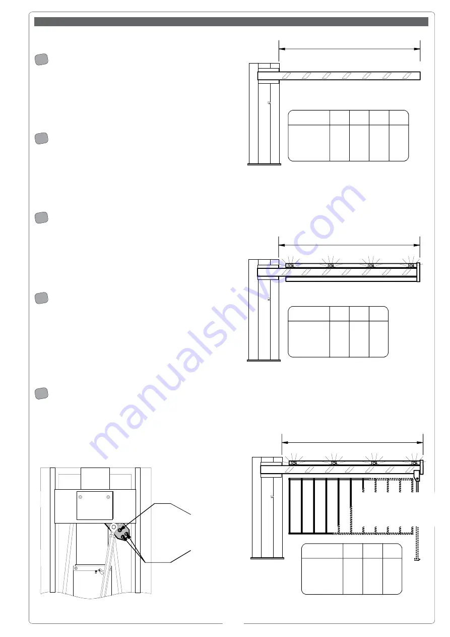
background image

- 7 -

L

Posizione molle

Springs position

Position ressorts

Federneinstellung

Posiciòn resortes

m

<4

<5

<6

<6.5

1 A

1 A

1 B

1 A

1 B

L

Posizione molle

Springs position

Position ressorts

Federneinstellung

Posiciòn resortes

m

<4

<5

<6

1 A

1 B

1 A

1 B

L

Posizione molle

Springs position

Position ressorts

Federneinstellung

Posiciòn resortes

m

<4

<5

<6

1 B

1 A

2 B

1 B

con rastrrelliera o appoggio mobile

with rack or mobile support

avec tablier ou appui mobile

mit Schrankengitter oder feste Stütze

B

A

fissaggio molle
attach springs
fixation ressorts
Federnhalterung
enganche resortes

Bilanciamento asta - 

Gate rod balancing - Equilibrage barre - Stangeausgleich - Equilibracion barra

La barriera G6000 viene fornita di serie con entrambe le

molle montate sulla posizione B.

Se la configurazione finale della vostra barriera lo richiede (vedi
illustrazioni), sbloccare il motoriduttore e cambiare posizione alle
molle (conservare la molla eventualmente non utilizzata).

Per un eventuale bilanciamento fine, vedere la pagina seguente.

I

GB

E

D

F

Barrier G6000 is supplied with both springs installed in position B.

If the final configuration of your barrier requires a change in
the position of the springs (see illustrations), unlock the gear
motor and change the position of the springs (do not throw away
the spring if not used).
If  precise balancing of the barrier rod is required, see the next page.

La barrière G6000 est fournie de série avec le deux

ressorts montés sur la position B.
Si cela est nécessaire pour la configuration finale de la barrière
(voir illustrations), débloquer le motoréducteur et changer la
position du ressort (garder le ressort éventuellement non utilisé).
Pour un éventuel équilibrage fin, voir la page suivante.

Die Schrank G6000 wird serienmäßig mit in

Position B montierten Federn geliefert.
Wenn es die endgültige Schrankenkonfiguration erfordern
sollte (siehe Abbildungen), den Getriebemotor entblocken und
die Federposition ändern (die eventuellen nicht verwendete
Feder aufbewahren).
Bei eventuell erforderlichem Feinausbalancieren, siehe nächste
Seite.

La barra G6000 se suministra de serie con ambos resortes

montados en la posición B.
Si la configuración final de su barrera lo requiere (ver figura),
desbloquear el motorreductor y cambiar la posición des resortes
(conservar el resorte en el caso de que no se haya utilizado).
Para un eventual equilibrado fino, ver la página siguiente.

Summary of Contents for G 6000

Page 1: ...anti choc 7 Lampe de mouvement 8 Clignotant de mouvement 9 S lecteur cl 10 Batterie d urgence 11 Colonnette pour photocellule 12 Photocellule de s curit 13 Colonnette pour lecteur de carta magn tique...

Page 2: ...er l applicazione del lampeggiatore su armadio ACCESSORI OPZIONALI Models G6000 Barrier with non reversible 24 V d c gear motor case in galvanised steel with enamel finish control panel and internal d...

Page 3: ...pplication d une photocellule sur l armoire G0469 Support pour l application du clignotant sur l armoire ACCESSOIRES EN OPTION Modelle G6000 Schranke mit selbsthemmendem 24 V Gleichstrom Getriebemotor...

Page 4: ...sforescente para las barras G0462 Apoyo fijo para las barras G0463 Apoyo m vil para las barras G0465 Estante de aluminio barnizado blanco para las barras G0467 Articulaci n para G0601 G0468 Soporte pa...

Page 5: ...finition galvanis e Il permet un blocage rapide et s r de la lisse D Le d blocage du motor ducteur grace un cin matisme sp cial s effectue au moyen d une cl personnalis e E Moteur en courant continu...

Page 6: ...el equipo Regular el alineado vertical y horizontal del hasta actuando en el tope mec nico B y en la palanca de transmisi n C I GB F D E 1 Predisponer en funci n de las medidas del grupo una plataform...

Page 7: ...on B If the final configuration of your barrier requires a change in the position of the springs see illustrations unlock the gear motor and change the position of the springs do not throw away the sp...

Page 8: ...GB I F D E To balance the barrier rod precisely proceed as follows 1 Unlock the gear motor p 5 ref D 2 Loosen locknuts B on tension rods A 3 Manually adjust the springs to increase decrease their tens...

Page 9: ...della barriera Funzione slave nel caso di due motori abbinati vedi pag 22 Aumento dell azione frenante della sbarra Tipo di comando apre chiude solo apertura ENGLISH This control board is powered by...

Page 10: ...n d une sortie 24V pendant les phases de mouvement et en position de fermeture Fonctionnement slave en cas de deux moteurs associ s voir page 22 Augmentation de l action de freinage de la barri re DEU...

Page 11: ...Los dispositivos de mando son a baja tensi n 24V protegidos por fusible a 2A La potencia total de los accesorios a 24V no debe superar los 20W Seguridad Las fotoc lulas pueden estar conectadas y predi...

Page 12: ...keit 8 Code Speichertast 9 Schlie automatik Anzeige LED Funkcode 10 Steckverbinder Stromversorgung Motor 11 Steckverbinderf rBatterieladeger t Anschlu LB35 12 Steuerart Wahljumper f r Taste auf 2 7 D...

Page 13: ...4V output voltage on 10 E terminals when the barrier is in motion and in the barrier s closed position enabled 3 OFF 24V output voltage on 10 E terminals when the barrier is in motion enabled 4 ON Ope...

Page 14: ...g der Klemmen 10 E bei Schrankenlauf zugeschaltet 4 ON Bedienung vom Steuerpult zugeschaltet 5 ON Vorblinker beim ffnen und Schlie en zugeschaltet 6 ON Hindemisaufnahme bei Motor am Endanschlag zugesc...

Page 15: ...24V Gleichstrom bei Stromversorgung 24V Gleichstrom Alimentaci n accesorios max 40W 24V a c con alimentaci n a 230V a c 24V d c con alimentaci n a 24V d c Pulsante stop N C Pushbutton stop N C Bouton...

Page 16: ...ur ralentissement en ouverture Anschlu Microschalter verlangsamen ffnung Conexi n microinterruptor deceleraci n en apertura Collegamento microinterruttore rallentamento in chiusura Connection microswi...

Page 17: ...9 MHz TOP and TAM series position the jumper connection on circuit card AF43S as shown on the sheet Pour les metteurs de fr quence 433 9 AM s rie TOP et s rie TAM il faut positionner le pontet sur la...

Page 18: ...1 and 2 as per fig A see fig B for any subsequent settings on different channels La premi re codification doit tre effectu e en maintenant les cavaliers en position pour les canaux 1 et 2 comme d apr...

Page 19: ...dip C et le canal sur D P1 CH1 et P2 CH2 saisie de d faut Stellen Sie den Code auf den Dip Switch C und den Kanal auf D P1 CH1 und P2 CH2 Grundeinstellung plantear el c digo en el dip switch C y el ca...

Page 20: ...re simply repeat the procedure described above FRANCAIS Appuyer sur la touche PROG sur la carte de base le led de signalisation clignote voir fig 1 avec une touche du emetteur on envoie le code le led...

Page 21: ...max vedi disegno a lato I To adjust the motion speed move the A faston connector For slowdowns move the B faston connector Ex max speed during opening and closing max deceleration see drawing opposit...

Page 22: ...de blocage interd pendent de la fa on indiqu e sur la figure F 1 Auf einem der beiden Steuerger te den Dip Switch 7 auf ON stellen wodurch dieser Motor zum gesteuerter Motor Slave wird 2 Nur auf der M...

Page 23: ...23 NOTE NOTES NOTE HINWEIS NOTA...

Page 24: ...R L ______COLOGNO M MI 39 02 26708293 39 02 25490288 CAME SUD S R L ___________________NAPOLI 39 081 7524455 39 081 7529109 CAME AMERICA L L C ____________MIAMI FL 1 305 5930227 1 305 5939823 CAME AU...

Reviews: