
119GV72
119GV72 ver.1.1
1.1 01/2012
www.came.com
ATTACHMENT FLANGE FOR SEMI-ELLIPTICAL ARM
ATTACHMENT FLANGE FOR SEMI-ELLIPTICAL ARM
EN
A -
Flange cover
B -
Attachment fl ange
C -
Mid plate
D -
Arm end-cap
E -
Semi-elliptical barrier arm L = 3m
F -
Anti-impact profi le
G -
Channel cover profi les
H -
L
uminous cord
I -
Luminous cord power supply cable
L -
Refl ective adhesive strips
M
- Balancing spring Ø 50 mm
N
- internal barrier-arm reinforcement
Installation
Installation
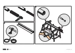
1 -
Calculate the am length (A) and that of the anti-impact profi le (C)
by using as reference the passage width length (B). If necessary,
trim off any excess.
2 -
Fit the reinforcement and the anti-impact profi le into the barrier
arm; trim any excess profi le.
3 -
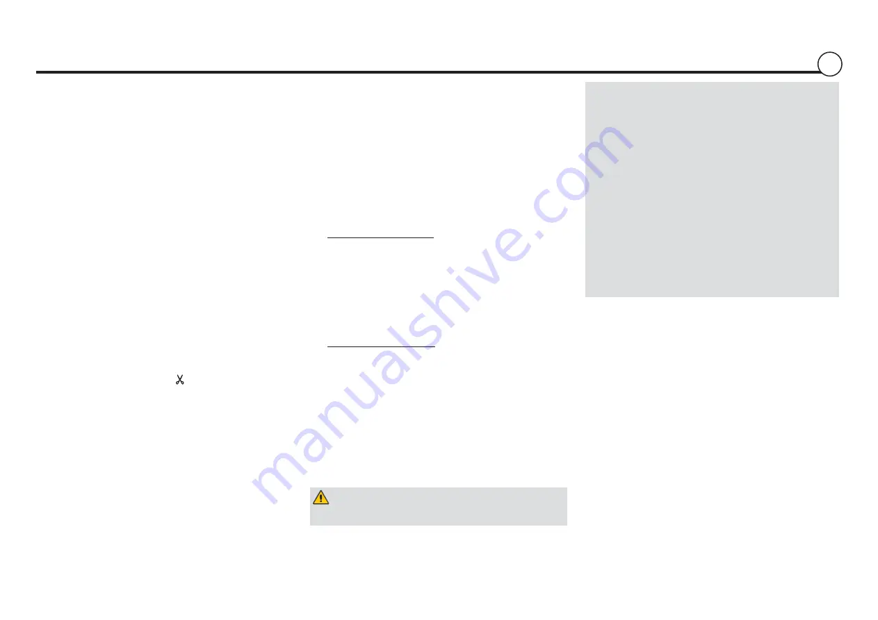
The luminous cord may be cut only at the points indicated by
the scissors (i.e. at each meter) .
Length of cord = L x 2 + 0.5 m
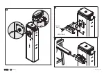
4 -
Insert the insulation cap into one of the two ends of the luminous
cord. Insert by pressure the luminous cord into the arm raceway,
as shown in the fi gure.
.
5 -
Insert the power cable through the central hole in the
transmission arm plate. Perforate the control panel at one of
the pre-perforated points and fi t the cable gland; insert and
connect the cable to terminal 10-E6
.
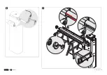
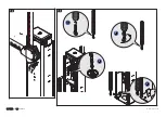
6 -
Position the mid plate and the attachment flange to the
transmission shaft, using the screws.Do not tighten the screws
to facilitate the later insertion of the arm.
.
7 - Insert and fasten the arm into the attachment cover, while
being careful about the cord's power supply cable.
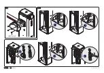
8 -
Connect the power cable jack to the luminous cord. If the
luminous cord does not work invert/turn the jack, then isolate
the junction point with a thermo shrinking sheath.
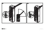
9 -
Cut the cable cover profi les to the right length and insert into the
arm raceway. Procedure to follow on both sides. Secure the cap
to the end of the arm and apply the refl ective adhesive strips.
10 -
Insert and fasten the (anti-shearing) fl ange cover onto the arm
attachment cover , using the screws.
11 -
Adjust the balancing screw:
- unhook the eyelet rod from the bracket (1);
- fully tighten the rod (2);
- fully tighten the spring to the attachment lug (3);
- re-hook the rod to the bracket (4);
- fasten the lug nut to the spring (5);
12 -
Release the gearmotor and position the arm vertically, then lock
it back into place.
13 -
Set up the balancing spring:
- fully tighten the eyelet rod under the spring (1, 2);
- tighten the spring on the anchoring lug which is hooked to the
transmission shaft (3);
- hook the rod to the bracket (4);
14 -
Release the gearmotor. Manually turn the balancing spring to
increase or reduce the traction force so that the arm balances
at 45°.
15 -
Fasten the lug nut and lock the gearmotor into place.
Semi-elliptical arm attachment flange complete with flange cover
and barrier arm end-cap.
Dismantling and disposal
Dismantling and disposal
Before dismantling and disposing always do the following:
check the applicable laws specific to your jurisdiction.
The components of the packaging (i.e. cardboard, plastic, etc.)
are solid urban waste and may be disposed of without much
trouble, simply by separating them for recycling.
Other components (i.e. electronic cards, remote control batteri-
es, etc. ) may contain hazardous substances. These must there-
fore be handed over the specially authorised disposal firms.
DO NOT DISPOSE OF IN NATURE!
The data and information in this manual may be changed at any
time and without prior notice.
Warning! When balancing procedures are fi nished, LUBRICA-
TE THE SPRINGS WITH SPRAY GREASE!
Summary of Contents for G03003
Page 2: ...119GV72 119GV72 ver 1 1 1 1 01 2012 www came com l 24V ELI LIG HT by ELIO S FLEXILIG HT CE...
Page 3: ...119GV72 119GV72 ver 1 1 1 1 01 2012 www came com UNI5931 M8x20 UNI5931 M8x12...
Page 4: ...119GV72 119GV72 ver 1 1 1 1 01 2012 www came com...
Page 5: ...119GV72 119GV72 ver 1 1 1 1 01 2012 www came com 5 4 1 2 3 UNI6954 3 9x19...
Page 6: ...119GV72 119GV72 ver 1 1 1 1 01 2012 www came com 3 4 1 2...
Page 7: ...119GV72 119GV72 ver 1 1 1 1 01 2012 www came com 45 4 5...


