background image

- pag. 

- pag. 

- pag. 

- pag. 

- pag. 

5

5

5

5

5

 - english -

 - english -

 - english -

 - english -

 - english -

DESCRIPTION OF ASSEMBLY PROCEDURE

DESCRIPTION OF ASSEMBLY PROCEDURE

DESCRIPTION OF ASSEMBLY PROCEDURE

DESCRIPTION OF ASSEMBLY PROCEDURE

DESCRIPTION OF ASSEMBLY PROCEDURE

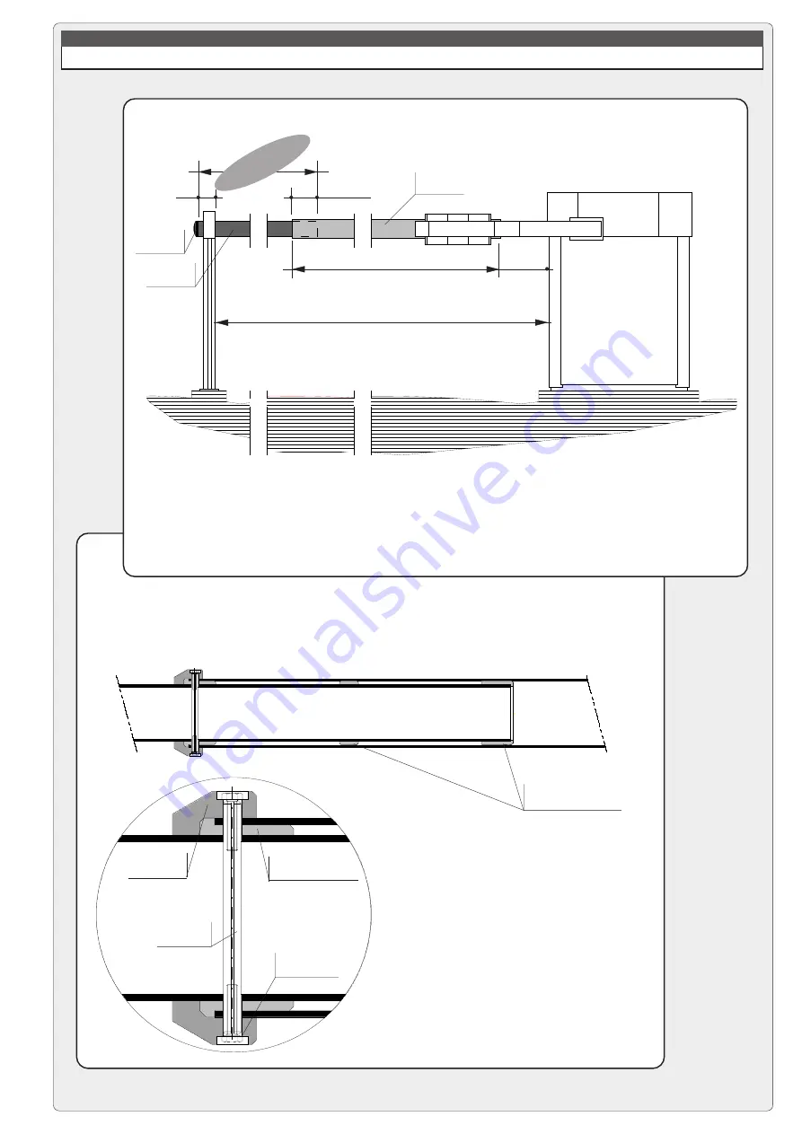
2 - PRELIMINARY ASSEMBLY OF THE BARRIER BAR

a) use the indicated formula to determine length LTP of the rear tube
(Ø100 mm), cut the tube to the correct length and install the end cap.

fixed length 6200 mm

d

epth of

insertion

b) assemble the barrier bar by
sliding the rear tube into the front
tube (Ø120 mm, fixed length of 6200
mm) and inserting the centring pin;
next, install and tighten the two
mounting jaws;

150

500


L

N

300

FRONT TUBE

REAR TUBE

END CAP

L

TP

 = L

N

 - 5850

mounting screw
on mounting jaw

mounting jaw

centring pin

thrust ring to be latched
onto the centring pin

FRONT TUBE

REAR TUBE

thrust rings already installed on
Ø100 mm rear tube

Summary of Contents for G12000 Series

Page 1: ...Documentazione Tecnica 56 rev 2 0 03 2001 CAME CANCELLI AUTOMATICI 119G56 GB SERIE GARD G12000 CANCELLI AUTOMATICI ROAD BARRIER...

Page 2: ...barrier Description Motorised barrier for control of passages with width of up to 12 m Designed and built entirely by CAME S p A meets UNI 8612 safety standards with IP54 degree of protection Guarant...

Page 3: ...rectangular plates which are assembled as needed 5 RELEASE SYSTEM Manual with PVC handle and cord in self lubricating sheath safety lock 6 HOUSING Load bearing structure in steel profiles and externa...

Page 4: ...base is perfectly level and that the electrical cables for the unit protrude in the area indicated b detach the mounting base from the housing and mount the anchor stays on the base apply grease and...

Page 5: ...f the rear tube 100 mm cut the tube to the correct length and install the end cap fixed length 6200 mm depth of insertion b assemble the barrier bar by sliding the rear tube into the front tube 120 mm...

Page 6: ...ing base c position and mount the fixed support for the barrier bar and make sure it is in perfect longitudinal alignment with the housing g check for misalignment and adjust if necessary then firmly...

Page 7: ...the support alternatively on the left and right until the bar shows signs of raising N B if not all the counterweight plates are used they must be fixed with a hose clamp to avoid possible release dur...

Page 8: ...arged automatically refer to instruction sheet Flashing signal light when bar is in motion Plug in radio receiver Other functions available Automatic closing The automatic closing timer is automatical...

Page 9: ...t STOP button N C see selection functions OPEN button N O Connector N O radio and or pushbutton See DIP 2 for command type Button operation closure only Contact N C for re opening during closure if no...

Page 10: ...vated 2 2 3 funcion 24V output during movement and in the closed position ON OFF activated deactivated 3 3 3 function 24V output during movement ON OFF deactivated activated 3 3 9 9 function total sto...

Page 11: ...LACI N TRIMMERS EINTELLUNG TRIMMERS R GLAGE TRIMMERS TRIMMERS ADJUSTMENT REGOLAZIONE TRIMMERS SENS T C A Trimmer SENS Adjustment of amperometric sensitivity min max Trimmer T C A Adjustment automatic...

Page 12: ...first encoding operation must be carried out whilst keeping the jumpers positioned for channels 1 and 2 as per fig A see fig B for any subsequent settings on different channels T262L M T302L M P1 P2...

Page 13: ...1 P2 CH2 P3 CH3 P4 CH4 1 2 3 4 5 6 7 8 9 10 C P1 P2 P3 P4 T432S set the code to dip switch C and channel to D P1 CH1 and P2 CH2 default setting T432M T312M 1 2 3 4 5 6 7 8 9 10 1 2 3 4 C D P1 P2 P2 CH...

Page 14: ...the lights up of LED sign the code stored Fig 2 IMPORTANT Do not store the code on the circuit card unless the barrier is closed N B If you wish to change the code on your transmitters in the future...

Page 15: ...al board for the pilot motor in the normal CONNECTIONS FOR 2 COMBINED MOTORS CONTROLLED TOGETHER ZL37B CONTROL PANEL 1 On one of the two control panels set Dip 7 to ON in order to select the motor con...

Page 16: ...33 01 46130505 33 01 46130500 CAME GMBH________KORNTAL BEI STUTTGART 49 07 11839590 49 07 118395925 CAME GMBH____________SEEFELD BEI BERLIN 49 03 33988390 49 03 339885508 CAME PL SP ZO O_____________...

Page 17: ...Gate automation equipment must be installed in accordance with all current legislation namely Machinery Directive 98 37 EC and BS EN12453 Important Information BRUNDLE...

Reviews: