


- pag.
- pag.
- pag.
- pag.
- pag.
8
8
8
8
8
- english -
- english -
- english -
- english -
- english -
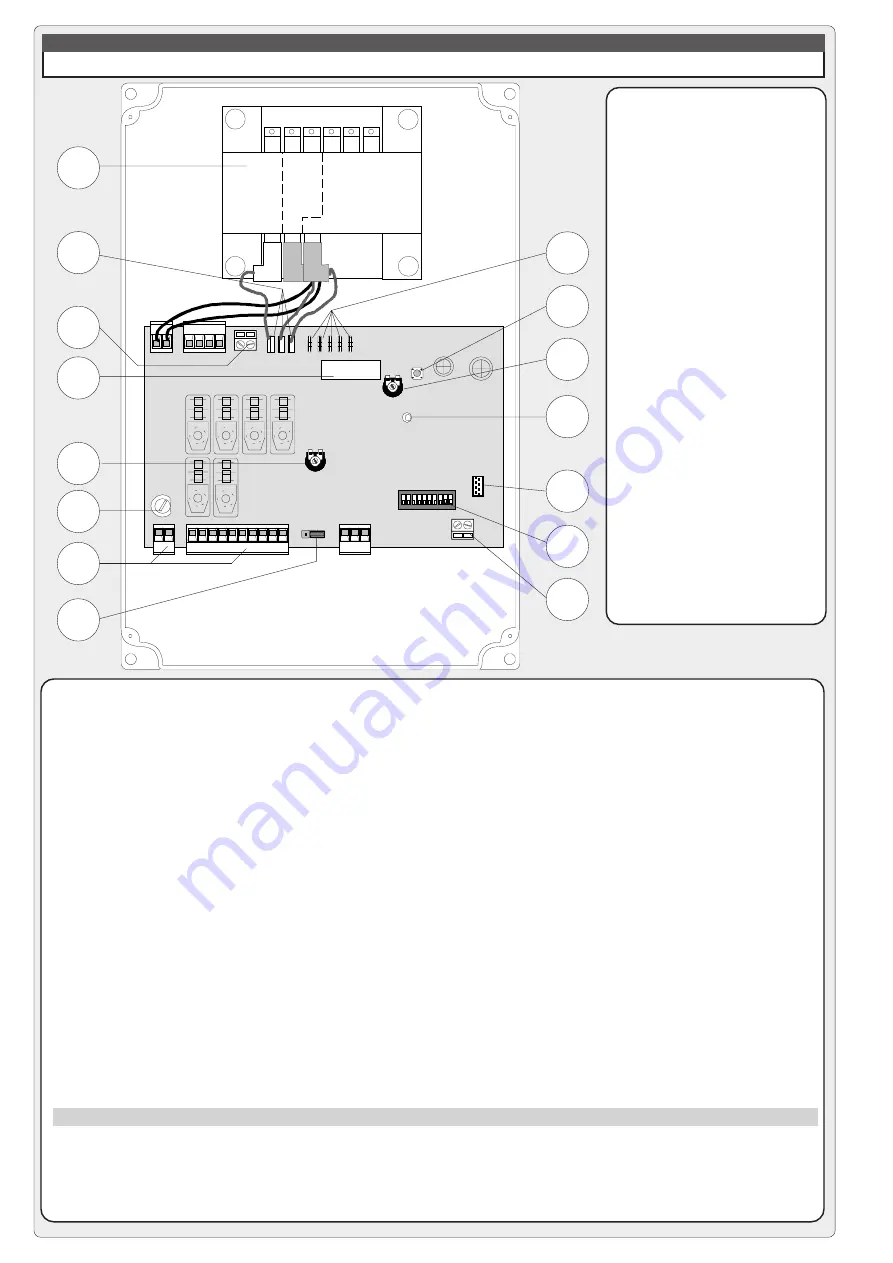
MAIN COMPONENTS
1) Transformer
2) Connectors for power
supply motor
3) Terminal block for motor
connections
4) 2A accessories fuse
5) Amperometric sensitivity
adjustment (trimmer
SENS)
6) 3,15A line fuse
7) Terminal block for external
connections
8) Jumper for selection of
type of control for button
in 2-7
9) Connectors for connection
to battery charger LB35
10) Button for memorizing
code numebers
11) Automatic closing time
adjustment (trimmer TCA)
12) Radio code / automatic
closing signal LED
13) Radiofrequency board
socket (see table pag. 11)
14) "Funcion selection" dip-
switch
15) Terminal block for antenna
connections
DESCRIPTION & CONTROL LOGIC
ZL37B CONTROL PANEL
This control board is powered by
230V a.c. across terminals L1 and
L2, and is protected by a 3.15A fuse
on the main power line.
Control systems are (24) powered by
low voltage and protected with by a
2A fuse.
The total power consumption of 24V
accessories must not exceed 40 W.
Safety
Photocells can be connected to
obtain:
a)
Re-opening during the closing
cycle;
b)
Total stop: the movement of the bar
is interrupted, and the automatic
closure cycle is disactivated. Use the
keyboard or the radio transmitter to
resume movement of the bar;
c)
Immediate closure (the bar is
lowered automatically after the
vehicle has passed the safety
devices, on the terminals 2-C5 of the
control panel;
- Amperometric safety device: see
NOTE;
- Fixed operating time of 20 sec.
Accessories which can be
connected to this unit
- LB35 board, used to power the
automation system using battery
power in case of a power failure. When
the power supply is restored, the
batteries are recharged automatically
(refer to instruction sheet);
- Flashing signal light when bar is in
motion;
- Plug-in radio receiver.
Other functions available
- Automatic closing: The automatic
closing timer is automatically activated
at the end of the opening cycle. The
preset, adjustable automatic closing
time is automatically interrupted by the
activation of any safety system, and
is deactivated after a total stop
command or in case of power failure;
- Obstacle detection: When the motor
is stopped (bar is closed, open or half-
open after an emergency stop
command), the transmitter and the
control pushbutton will be deactivated
if an obstacle is detected by one of the
safety devices (for example, the
photocells);
- “Human presence” operation;
- Flashing light activated before
opening and closing cycle begins;
- Activation of a 24V output signal
during the movement phases and in
the closed position;
- "Slave" operation when two motors
are used in combination (see page
15);
- Function that increases the braking
action on the barrier;
- Selection of command sequence:
-open-close-reverse;
-open only.
Adjustments
- Trimmer TCA = Automatic closing
time: 0" to 120";
- Trimmer SENS = Sensitivity of
amperometric safety system: min/
max.
Important
: Shut off the mains power
and disconnect the batteries before
servicing the inside of the unit.
When an obstacle is encountered, the amperometric locking device intervenes as follows:
a) if in the aperture phase, the bar stops;
b) if in the closure phase, the movement of the bar is reversed.
N.B.: In situation (b), if an obstacle is detected three times, the bar stops during aperture, and automatic closure is
disactivated.
Use the keyboard or the radio transmitter to resume movement of the bar.
NOTA
2
1
3
4
5
6
7
8
9 10
0
Rall.
Vel.
7
4
C
O
M
Velocità
Speed
Vitesse
Geschw.
Velocidad
Rallentamento
Deceleration
Ralentissement
Geschw.
Abnahme
Deceleración
"B"
"A"
2
4
1
6
7
8
14
13
12
11
15
10
9
3
5


