background image

p. 

2

 - M

an

u

al

 c

od

e: 

F

A

0

0

1

2

4

-E

N

FA

0

0

1

2

4

-E

N

 v.


3

- 04/

2

0

17 - © C

am

e S

.p.

A

. - T

h

e m

an

u

al

's c

onte

nts m

ay b

e e

d

ite

d at a

ny ti

m

e w

ith

ou

t n

oti

ce

.

WARNING!

Important safety instructions.

READ CAREFULLY

P

REMISE

• T

HIS


PRODUCT


MUST


ONLY


BE


USED


FOR


THE


PURPOSE


FOR


WHICH


IT


WAS


DE

-

SIGNED

. A

NY


OTHER


USE


IS


DANGEROUS

. CAME S.

P

.A. 

IS


NOT


LIABLE


FOR


ANY


DAMAGE


CAUSED


BY


IMPROPER

WRONGFUL


AND


UNREASONABLE


USE

. • P

RODUCT


SAFETY


AND


CORRECT


INSTALLATION


ARE


SUBJECT


TO


RESPECTING


THE


PRODUCT

'

S


TECHNICAL


CHARACTERISTICS


AND


THE


CORRECT


INSTALLATION


PROCEDURE

IN


LINE


WITH


PROFESSIONAL


STANDARDS

SAFETY


REGULATIONS


AND


USAGE


SPECIFICATIONS

AS


SET


OUT


IN


THE


TECHNICAL


DOCUMENTATION


THAT


COMES


WITH


THE


PRODUCT

. • 

K

EEP


THESE


PRECAUTIONS


TOGETHER


WITH


THE


INSTALLATION


AND


USAGE


MANUALS


THAT


COME


WITH


THE


OPERATOR


SYSTEM

.

B

EFORE


INSTALLING

(C

HECK


THE


CONTENTS

IF


SOMETHING


IS


MISSING

DO


NOT


CONTINUE


UNTIL


YOU


HAVE


COMPLIED


WITH


ALL


SAFETY


PROVISIONS

)

• F

ITTING


AND


TESTING


MUST


ONLY


BE


PERFORMED


BY


QUALIFIED


TECHNICIANS

 • L

AY


THE


CABLES

INSTALL


AND


CONNECT


UP


THE


PRODUCT

AND


RUN


TESTING


FOLLOWING


PROFESSIONAL


PROCEDURES


IN


COMPLIANCE


WITH


THE


STANDARDS


AND


REGULATIONS


IN


FORCE

 • B

EFORE


BEGINNING


ANY


OPERATION

READ


ALL


INSTRUCTIONS


CAREFULLY

INCORRECT


INSTALLATION


MAY


CAUSE


SERIOUS


HARM


TO


PEOPLE


OR


PROPERTY

 • 

M

AKE


SURE


THE


BOOM


IS


IN


GOOD


MECHANICAL


ORDER

BALANCED


AND


ALIGNED

AND


THAT


IT


OPENS


AND


CLOSES


PROPERLY

. I

F


REQUIRED

FIT


SUITABLE


PROTECTIVE


DEVICES


OR


USE


SUITABLE


ADDITIONAL


SAFETY


SENSORS

 • I

F


THE


OPERATOR


IS


TO


BE


INSTALLED


AT


A


HEIGHT


OF


OVER

 2.5 

M


FROM


THE


GROUND


OR


OTHER


ACCESS


LEVEL

MAKE


SURE


YOU


HAVE


ANY


NECESSARY


PROTECTIVE


DEVICES


OR


WARNINGS


IN


PLACE

 • 

M

AKE


SURE


THAT


THE


OPENING


AUTOMATIC


BARRIER


DOES


NOT


CREATE


A


HAZARD

 • 

D

O


NOT


INSTALL


THE


OPERATOR


UPSIDE


DOWN


OR


ON


ELEMENTS


THAT


COULD


BEND

I

F


NECESSARY

ADD


SUITABLE


REINFORCEMENTS


TO


THE


ANCHORING


POINTS

 • M

AKE


SURE


THE


TEMPERATURE


RANGE


SHOWN


ON


THE


OPERATOR


IS


SUITABLE


FOR


THE


INSTALLATION


SITE

 • D

O


NOT


INSTALL


ON


SLOPING


OR


UNEVEN


SURFACES

 • M

AKE


SURE


ANY


SPRINKLER


SYSTEMS


CANNOT


WET


THE


OPERATOR


FROM


THE


GROUND


UP

.

I

NSTALLATION

• S

UITABLY


SECTION


OFF


AND


DEMARCATE


THE


ENTIRE


INSTALLATION


SITE


TO


PRE

-

VENT


UNAUTHORISED


PERSONS


FROM


ENTERING


THE


AREA

ESPECIALLY


MINORS


AND


CHILDREN

 • B

E


CAREFUL


WHEN


HANDLING


OPERATORS


THAT


WEIGH


OVER

 20 

KG

I

F


NEED


BE

USE


PROPER


SAFETY


HOISTING


EQUIPMENT

 • T

HE

 CE-

MARKED


SAFETY


DEVICES

  (

PHOTOCELLS

STEPPING


PLATES

SAFETY


EDGES

EMERGENCY


BUTTONS

ETC

.) 

MUST


BE


FITTED


IN


COMPLIANCE


WITH


PROFESSIONAL


STANDARDS


AND


THE


REGULATIONS


IN


FORCE

TAKING


INTO


ACCOUNT


THE


ENVIRONMENT

TYPE


OF


SER

-

VICE


REQUIRED


AND


THE


WORKING


FORCES


APPLIED


TO


THE


MOVING


BARRIERS

. A

NY


POINTS


AT


WHICH


THERE


IS


A


RISK


OF


CRUSHING

SHEARING


OR


CONVEYING


MUST


BE


SENSOR

-

PROTECTED

 • A

NY


RESIDUAL


RISKS


MUST


BE


CLEARLY


SHOWN

 • A

LL


OPENING


CONTROLS

 (

BUTTONS

KEY

-

SWITCH


SELECTORS

MAGNETIC


READERS

ETC

.) 

MUST


BE


INSTALLED


AT


LEAST

 1.85 

M


FROM


THE


PERIMETER


OF


THE


BARRIER

'

S


WORKING


AREA

OR


WHERE


THEY


CANNOT


BE


REACHED


FROM


THE


OUTSIDE


THROUGH


THE


BARRIER

. A

NY


DIRECT


CONTROLS

 (

BUTTONS

TOUCH


PANELS

ETC

.) 

MUST


BE


INSTALLED


AT


LEAST

 1.5 

M


FROM


THE


GROUND


AND


MUST


NOT


BE


ACCESSIBLE


TO


UNAUTHORISED


PERSONS

 • T

HE


AUTOMATIC


BARRIER


MUST


BEAR


VISIBLE


IDENTIFICA

-

TION


DATA

. • B

EFORE


CONNECTING


THE


BARRIER


TO


THE


POWER


SUPPLY

MAKE


SURE


THAT


THE


IDENTIFICATION


DATA


CORRESPOND


TO


THE


MAINS


DATA

 • T

HE


AUTOMATIC


BARRIER


MUST


BE


CONNECTED


TO


AN


EFFECTIVE


EARTHING


SYSTEM


THAT


COMPLIES


WITH


LEGAL


STANDARDS

.

• T

HE


MANUFACTURER


DECLINES


ALL


LIABILITY


FOR


USE


OF


NON

-

ORIGINAL


PROD

-

UCTS

WHICH


WOULD


ALSO


RESULT


IN


WARRANTY


LOSS

 • A

LL


HOLD

-

TO

-

RUN


CON

-

TROLS


MUST


BE


FITTED


IN


PLACES


FROM


WHICH


THE


MOVING


BARRIER


AND


TRANSIT

/

MANOEUVRING


AREAS


ARE


VISIBLE

 • W

HERE


MISSING

APPLY


A


PERMANENT


SIGN


SHOWING


THE


POSITION


OF


THE


RELEASE


DEVICE

 • B

EFORE


DELIVERING


THE


PRODUCT


TO


THE


USER

MAKE


SURE


THE


SYSTEM


IS


COMPLIANT


WITH


STANDARDS

 EN 12453 

AND

 EN 12445 (

REGARDING


IMPACT


FORCES

), 

AND


ALSO


MAKE


SURE


THE


SYSTEM


HAS


BEEN


PROPERLY


ADJUSTED


AND


THAT


ANY


SAFETY

PROTECTION


AND


MANUAL


RELEASE


DEVICES


ARE


WORKING


PROPERLY

 • A

PPLY


WARNING


SIGNS


WHERE


NECES

-

SARY


AND


IN


A


VISIBLE


PLACE

 (

E

.

G

A


PANEL


ON


THE


BARRIER

).

U

SER


INSTRUCTIONS


AND


RECOMMENDATIONS

• K

EEP


BARRIER


OPERATION


AREAS


CLEAN


AND


FREE


OF


ANY


OBSTRUCTIONS

. M

AKE


SURE


THE


OPERATING


FIELD


OF


THE


PHOTOCELLS


AND


MAGNETIC


COILS


IS


CLEAR


OF


ANY


OBSTRUCTIONS

 • D

O


NOT


ALLOW


CHILDREN


TO


PLAY


WITH


FIXED


COMMANDS

OR


TO


LOITER


IN


THE


BARRIER


MANOEUVRING


AREA

. K

EEP


ANY


REMOTE


CONTROL


DEVICES


(

TRANSMITTERS

OR


ANY


OTHER


COMMAND


DEVICE


OUT


OF


THE


REACH


OF


CHILDREN

TO


PREVENT


THE


OPERATOR


FROM


BEING


ACCIDENTALLY


ACTIVATED

 • T

HE


APPARA

-

TUS


MAY


BE


USED


BY


CHILDREN


OF


EIGHT


YEARS


AND


ABOVE


AND


BY


PEOPLE


WITH


PHYSICAL


OR


COGNITIVE


DISABILITIES

OR


THOSE


LACKING


EXPERIENCE


OR


RELEVANT


KNOWLEDGE

PROVIDED


THEY


ARE


CLOSELY


SUPERVISED


OR


ONCE


THEY


HAVE


BEEN


PROPERLY


INSTRUCTED


ON


HOW


TO


USE


THE


APPARATUS


SAFELY


AND


ON


THE


POTEN

-

TIAL


HAZARDS


INVOLVED

. C

HILDREN


MUST


NOT


PLAY


WITH


THE


APPARATUS

. U

SER


CLEANING


AND


MAINTENANCE


MUST


NOT


BE


PERFORMED


BY


UNSUPERVISED


CHILDREN


• F

REQUENTLY


CHECK


THE


SYSTEM


FOR


ANY


MALFUNCTIONS


OR


SIGNS


OF


WEAR


AND


TEAR


OR


DAMAGE


TO


THE


MOVING


STRUCTURES

OPERATOR


COMPONENTS

ANCHOR

-

ING


POINTS


AND


DEVICES

CABLES


AND


ACCESSIBLE


CONNECTIONS

. K

EEP


ANY


JOINTS


(

HINGES

AND


FRICTION


POINTS

 (

BOOM


FLANGE

CLEAN


AND


LUBRICATED

 • P

ERFORM


FUNCTIONAL


CHECKS


ON


THE


PHOTOCELLS


EVERY


SIX


MONTHS

. A

LWAYS


MAKE


SURE


THE


PHOTOCELL


GLASS


COVERS


ARE


CLEAN

 (

USE


A


DAMP


CLOTH

DO


NOT


USE


SOL

-

VENTS


OR


CHEMICALS


THAT


COULD


DAMAGE


THE


DEVICES

) • I

F


REPAIRS


OR


MODIFICA

-

TIONS


ARE


REQUIRED


TO


THE


SYSTEM

RELEASE


THE


OPERATOR


AND


DO


NOT


USE


IT


UNTIL


THE


SAFETY


CONDITIONS


HAVE


BEEN


RESTORED

 • C

UT


OFF


THE


ELECTRICAL


POWER


SUPPLY


BEFORE


RELEASING


THE


OPERATOR


FOR


MANUAL


OPENINGS

. R

EAD


THE


INSTRUCTIONS

 • I

F


THE


POWER


SUPPLY


CABLE


IS


DAMAGED

IT


MUST


BE


REPLACED


BY


THE


MANUFACTURER


OR


ITS


AUTHORISED


TECHNICAL


ASSISTANCE


SERVICE


OR

IN


ANY


CASE

BY


SIMILARLY


QUALIFIED


PERSONS

TO


PREVENT


ANY


RISK

 • U

SERS


MUST


NOT


PERFORM


ANY


OPERATIONS


THAT


ARE


NOT


EXPRESSLY


REQUIRED


OF


THEM


AND


WHICH


ARE


NOT


LISTED


IN


THE


MANUALS

. F

OR


ANY


REPAIRS

MODIFICATIONS

ADJUSTMENTS


AND


NON

-

SCHEDULED


MAINTENANCE

PLEASE


CONTACT


THE


TECHNICAL


ASSISTANCE


SERVICE

 • L

OG


THE


WORK


IN


THE


PERIODIC


MAINTENANCE


LOG

.

F

URTHER


RECOMMENDATIONS


FOR


ALL

• K

EEP


AWAY


FROM


AND


DO


NOT


LOITER


NEAR


THE


BARRIER


BOOM


OR


MOVING


MECHANICAL


PARTS

 • D

O


NOT


ENTER


THE


AREA


OF


OPERATION


WHEN


THE


BARRIER


IS


MOVING

 • D

O


NOT


COUNTER


OR


OBSTRUCT


THE


OPERATOR

'

S


MOVEMENT


AS


THIS


COULD


CAUSE


DANGER

 • A

LWAYS


PAY


SPECIAL


ATTENTION


TO


ANY


DANGEROUS


POINTS

WHICH


MUST


BE


LABELLED


WITH


SPECIFIC


PICTOGRAMS


AND

/

OR


BLACK


AND


YELLOW


STRIPES

 • W

HEN


USING


A


SELECTOR


SWITCH


OR


A


HOLD

-

TO

-

RUN


CONTROL

KEEP


CHECKING


THAT


THERE


ARE


NO


PERSONS


WITHIN


THE


OPERATING


RANGE


OF


ANY


MOVING


PARTS

UNTIL


THE


CONTROL


IS


RELEASED

 • T

HE


BARRIER


MAY


MOVE


AT


ANY


TIME


AND


WITHOUT


WARNING

 • A

LWAYS


CUT


OFF


THE


POWER


SUPPLY


BEFORE


PERFORMING


ANY


MAINTENANCE


OR


CLEANING


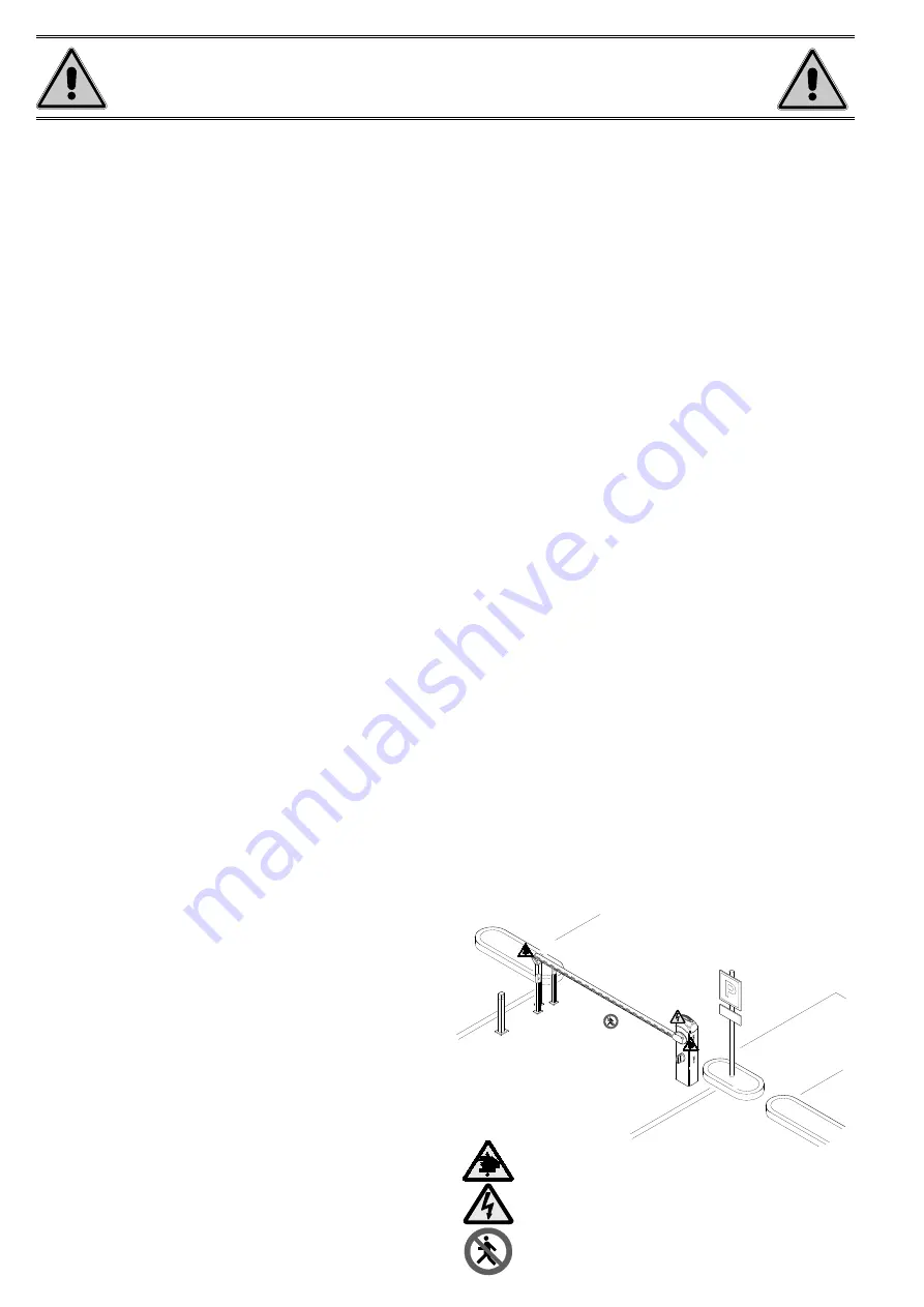
Danger of hand crushing

Danger! High voltage.

No transiting while the barrier is moving

Summary of Contents for G4040EZ

Page 1: ...AUTOMATIC BARRIERS FA00124 EN English EN INSTALLATION AND OPERATION G4040EZ...

Page 2: ...COMPLIES WITH LEGAL STANDARDS THE MANUFACTURER DECLINES ALL LIABILITY FOR USE OF NON ORIGINAL PROD UCTS WHICH WOULD ALSO RESULT IN WARRANTY LOSS ALL HOLD TO RUN CON TROLS MUST BE FITTED IN PLACES FROM...

Page 3: ...to fit accessories Intended use The automatic barrier is designed to be used in public and private parking facilities Any installation and use other than that specified in this manual is forbidden Li...

Page 4: ...over 6 Cabinet 7 Release lock 8 Inspection hatch lock 9 Rod 10 Inspection hatch 11 Control panel 12 Boom adjustment mechanical stop 13 Lever arm 14 Gearmotor with encoder 15 EMC01 filter 16 Anchoring...

Page 5: ...through making sure they are protected from any mechanical damage Tools and materials Make sure you have all the tools and materials you need to install the product in complete safety and in complian...

Page 6: ...ing plate If the flooring does not provide a sturdy surface to fasten the cabinet to use a cement slab Dig a hole for the foundation frame Prepare the corrugated tubes you will need for the cables com...

Page 7: ...on arm release the gearmotor using the key turn the transmission arm lock the motor again fasten the rod to the opposite hole in the arm invert the motor phases M and N Left Right Fill the hole with e...

Page 8: ...ate with a screw Leave the screw loose to make it easier to insert the boom Attachment plate Intermediate plate Boom attachment cover Installing the barrier The cabinet should be installed with the in...

Page 9: ...ice Fit the boom into the attachment cover and fasten it using the screws Cut the groove covers to the required length and insert them in the boom conduits on both sides Insert the shockproof rubber p...

Page 10: ...with shockproof profile and 001G028401 luminous cord A A B B B C Boom with 001G0465 skirt A B B C C Boom with 001G028401 luminous cord and 001G0465 skirt A B B C C Boom with shockproof profile and 001...

Page 11: ...er nut and lock the gearmotor again Check the spring is working properly With the boom positioned vertically the spring is not taut With the boom positioned horizontally the spring is taut Hook the ey...

Page 12: ...0431177081 not supplied to the control signalling and safety device cables Description of parts 1 Transformer 2 Terminal board for power supply 3 Terminal board for transformer 4 Terminal board for g...

Page 13: ...y Power supply to accessories output a 24 V AC normally a 24 V DC when the emergency batteries are operating Max power 40 W Red White Blue Orange Ferrite Transformer 230 V AC 50 60 Hz 24 V DC gearmoto...

Page 14: ...abled from the function F 1 OPEN CLOSE INVERT step by step function from control device N O contact Keypad selector Transponder or card reader Insert the decoding card R700 for the TSP00 sensor or LT0...

Page 15: ...the safety devices C9 immediate closure with obstacle stand by during closing Closing the boom after a vehicle has passed through the operating area of the safety devices During closing the devices al...

Page 16: ...A The manual s contents may be edited at any time without notice Connecting the safety devices safety test At each opening and closing command the control board assesses the efficiency of the safety...

Page 17: ...and at about 89 when open The inspection hatch must be closed when the boom opens and closes To correct the vertical position of the boom lower the boom open the inspection hatch turn the mechanical...

Page 18: ...row keys for the submenus To increase or decrease a value use the arrow keys to exit the menu wait 10 seconds or press ESC then press ENTER to confirm Menu navigation then press ENTER Display Descript...

Page 19: ...Parameter transfer from Master to Slave F 56 Peripheral number F 60 Sleep mode F 61 Pre flashing function F 63 Change COM speed U 1 Entering a user with an associated command U 2 Delete a single user...

Page 20: ...19 Automatic closing time 0 Deactivated default 1 1 second 180 180 seconds The waiting time before the barrier closes automatically starts when the limit switch point is reached during opening The tim...

Page 21: ...m booms set the percentage from 65 to 75 F49 Managing serial connection 0 Deactivated default 1 Paired 2 Alternate 3 CRP To enable paired alternate or CRP operation F50 Save data 0 Deactivated default...

Page 22: ...boom 4 m 6 boom 6 m 8 boom 8 m To define the type of boom The choice of boom limits some of the speed slow down and calibration parameters This is so as to ensure that the operator functions correctly...

Page 23: ...ENTER to confirm the automatic travel calibration 3 The operator closes until it reaches the limit switch point 4 then the operator opens until it reaches the limit switch point Travel calibration Bef...

Page 24: ...firm deletion Deleting a single user When entering deleting users the flashing numbers that appear are numbers that can be used for other users you may want to enter maximum 25 users 2 Select a comman...

Page 25: ...uration data so that they can be reused with another electronic circuit board including in another system After saving the data remove the memory roll RELEASING THE BOOM This procedure must be done wi...

Page 26: ...he SLAVE operator Saving Follow the procedure for entering a user with the OPEN and PARTIAL PEDESTRIAN OPENING command on the MASTER panel Configuring the MASTER operator Select function F 49 Press EN...

Page 27: ...nel of the SLAVE operator only Important Activate the F 19 function automatic closing time on the panel on both operators Saving Follow the procedure for entering a user with the OPEN and STEP BY STEP...

Page 28: ...on The warning LED flashes quickly 4 12 Check the proper direction of travel The warning LED stays lit 13 13 Check the control devices The boom does not reach the limit switch 7 14 Replace the AF card...

Page 29: ...e edited at any time without notice Periodic maintenance Before doing any maintenance disconnect the power supply to prevent any hazardous situations caused by the boom moving accidentally Periodic ma...

Page 30: ...______________________________________________________ ________________________________________________________________________________________________ Fitter s stamp Name of operator Job performed on...

Page 31: ...d from other waste for recycling Always make sure you comply with local laws before dismantling and disposing of the product DISPOSE OF THE PRODUCT RESPONSIBLY DISMANTLING AND DISPOSAL Our products ar...

Page 32: ...ier Dosson di Casier Treviso Treviso Italy 33079 Sesto al Reghena Sesto al Reghena Pordenone Pordenone Italy 39 0422 4940 39 0422 4941 39 0434 698111 39 0434 698434 English English Manual code FA00124...

Reviews: