


p.
5
- M
an
u
al
c
od
e:
F
A
0
0
1
2
4
-E
N
FA
0
0
1
2
4
-E
N
v.
3
- 04/
2
0
17 - © C
am
e S
.p.
A
. - T
h
e m
an
u
al
's c
onte
nts m
ay b
e e
d
ite
d at a
ny ti
m
e w
ith
ou
t n
oti
ce
.
GENERAL INSTALLATION INSTRUCTIONS
⚠
Installation must be carried out by expert qualified personnel and in full compliance with the regulations in force.
Important! Using original CAME control and safety devices and accessories ensures easy installation and system maintenance.
Preliminary checks
⚠
Before installation:
• make sure the plate is anchored to a solid spot;
• make sure that the power supply network is equipped with a suitable all-pole disconnection device, which provides full cut-off in category III
power surge conditions, as required by the installation regulations (i.e. contacts are more than 3 mm apart);
• make sure that any connections inside the case (for protective circuit continuity) are fitted with extra insulation as compared to the other
conductive parts inside;
• set up suitable tubes and conduits for the electric cables to pass through, making sure they are protected from any mechanical damage.
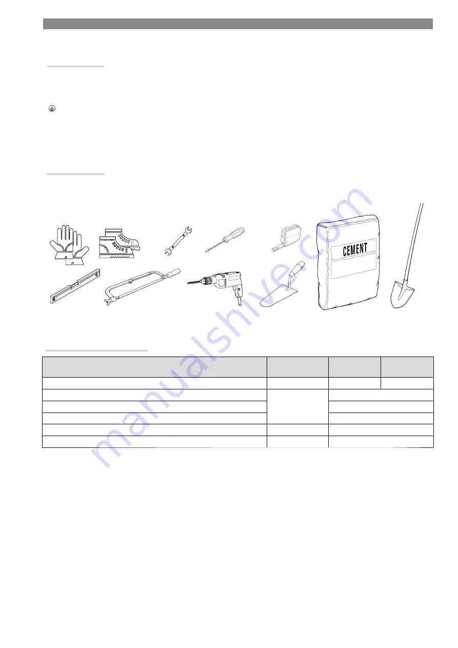
Tools and materials
Make sure you have all the tools and materials you need to install the product in complete safety and in compliance with the current regulations.
The following figure shows some basic equipment needed by the installer.
Types of cable and minimum sizes
Connection
Type of cable
Cable length
1 < 15 m
Cable length
15 < 30 m
Control panel power supply 230 V AC
H05RN-F
3G x 1.5 mm
2
3G x 2.5 mm
2
Photocell transmitters
FROR CEI 20-22
CEI EN
50267-2-1
2 x 0.5 mm
2
Receiver photocells
4 x 0.5 mm
2
Control and safety devices
2 x 0.5 mm
2
Antenna
RG58
max 10 m
Metal mass detector
(see product literature)
If cable lengths diff er from those specifi ed in the table, establish the cable sections depending on the actual power draw of the connected
devices and according to the provisions of regulation CEI EN 60204-1.
For multiple, sequential loads along the same line, the dimensions in the table need to be recalculated according to the actual power draw and
distances. When connecting products that are not specifi ed in this manual, please refer to the documentation provided with those products.


