Pa
g.
1
4
14
- M
an
u
al
c
od
e:
11
9
G
U
5
5
11
9
G
U
5
5
ve
r.
0
.2
0.
2
0
3
/2
0
10 © C
A
M
E c
an
ce
lli
auto
m
ati
ci
s.p.a. - T
h
e d
ata a
n
d i
nf
or
m
ati
on r
ep
orte
d i
n th
is
in
sta
lla
tio
n m
an
u
al
a
re s
u
sc
ep
tib
le to
c
h
an
g
e at a
ny ti
m
e a
n
d w
ith
ou
t o
b
lig
ati
on
o
n C
A
M
E c
an
ce
lli
auto
m
ati
ci
s.p.a. to n
otify u
se
rs.
ENGLISH
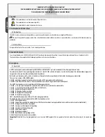
This product is engineered and manufactured by CAME cancelli automatici s.p.a.
and complies with current safety regulations.
The control panel works on 230V a.c. of power, 50/60Hz frequency.
Both command and control devices and accessories are 24V powered. Warning!
Accessories must not exceed 40 W overall.
The control unit is fi tted with an amperometric device which constantly regu-
lates the motor’s drive coeffi cient.
When the bar runs into an obstacle, the amperometric sensor immediately de-
tects an overcharge in the drive and redirects the gate’s direction of movement,
and:
- during opening: the bar stops;
- during closing: the bar reverses its direction until it opens completely; auto-
matic closure is thus activated.
Caution! after three consecutive direction reversals, the bar will remain up and
automatic closure will be discontinued. To close the gate, use the radio remote
control or the push-button.
All connections are protected by quick fuses, see table.
The card provides and controls the following functions:
- automatic closing after an open-command;
- immediate closure;
- pre-fl ashing by the motion indicator;
- obstacle detection when gate is still in any position;
- slave function;
- function that increases the braking action of the barrier.
The following command modes are possible:
- open/close;
- open/close and maintained action;
- open;
- complete stop.
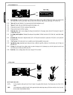
Apposite trimmers regulate:
- the automatic closing run time;
- the amperometric device’s detection sensitivity;
Optional accessories:
- Flashing Crown and Luminous band.
- bar open light marks the position of opening of the bar; it turns off after the
closing operation;
- LB38 Card, provides power supply through a battery, in case of a power out-
age. When power comes back on, it also recharges the batteries (see relative
technical literature).
Warning! Before acting on the machinery, cut off the main power supply and
disconnect any emergency batteries.
WARNING! The release
procedure may constitute a
hazard for the user when, for
whatever reason – the bar is fixed
improperly to the housing during
assembly, or the bar is cracked
or broken in an accident, and so
on – the tension springs no longer
provide balance!
These can thus
cause a brusque rotation of
the bar attachment and/or of
the bar itself
.
5.9 Manual release of the barrier
- Insert the key into the lock and turn it clockwise. Manually raise the bar and block it again by turning the key counter-clockwise.
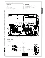
6 Description control panel
T E C H N I C A L F E AT U R E S
Power supply 230 V - 50/60 Hz
max. rated power 400 W
Power draw when idling 25 W
Max power of 24V accessories 40 W
Insulation rating II
Material ABS
F U S E S
protection: fuse type:
Motor/s 10 A-F
Electronic board
(power supply line)
3.15 A-F
Accessories 2 A-F
Control devices 630 mA-F

