background image

ENGLISH

WARNING!

Important instructions for the safety of people: 

READ CAREFULLY!

Foreword

• Use of the products must be restricted to its intended use 
(i.e. that for which it was expressly built for). Any other use is 
to be considered dangerous. Came Cancelli Automatici S.p.A. 
is not liable for any damage resulting from improper, wrongful 
or unreasonable use •  Keep these warnings with the installa-
tion and use manuals issued with the automated system.

Before installing 

(preliminary check: in case of a negative 

outcome, do not proceed before having 

complied with the safety obligations)

• Make sure that the parts you intend to automate are in 
good working order, and that they are  properly balanced 
and  aligned.  Also,  make  sure  that  proper  mechanical  stops 
are already in place • If the operator will be installed at a 
height  of  less  than  2.5  m  from  the  ground  or  other  access 
level, check whether you will need any protections and/or 
warnings • Any gate leaves, fi tted with pedestrian entrances, 
onto which you will install an operator, must have a blocking 
mechanism when the gate is in motion • Make sure that the 
opening of the automated gate is not an entrapment hazard 
as regards any surrounding fi xed parts • Do not mount the 
operator  upside  down  or  onto  any  elements  that  may  fold 
under its weight. If needed, add suitable reinforcements at 
the points where it is secured • Do not install onto gates on 
either an upward or downward slope (i.e. that are not on fl at, 
level ground) • Check that any lawn watering devices will not 
wet the gearmotor from the bottom up.

Installation

• Carefully section off the entire site to prevent unauthorised  
access, especially by minors and children • Be careful when 
handling operators that weigh more than 20 Kg (see installa-
tion manual). In such cases, employ proper weight handling 
safety equipment • All opening commands (e.g. buttons, key 
selectors, magnetic detectors, etc.) must be installed at least 
1.85 m from the gate’s area of operation perimeter - or where 
they cannot be reached from the outside of the gate. Also, 
the direct commands (e.g. push button, or proximity devices, 
etc.) must be installed at a height of at least 1.5 m and must 
not be accessible to the public • All ‘maintained action’ com-
mands, must be placed where the moving gate leaves, transit 
areas and driveways are completely visible • If missing, ap-
ply a permanent label that shows the position of the release 
mechanism • Before delivering to the client, verify that the 
system is EN 12453 (impact test) standard compliant. Make 
sure that the operator has been properly adjusted and that the 
safety and protection devices, as well as the manual release 

are working properly • Where necessary and in plain sight, 
apply the Warning Sings (e.g. gate plate).

Special instructions and 

advice for users

• Keep the gate’s area of operation clean and clear of any 
obstacles. Trim any vegetation that may interfere with the 
photocells • Do not allow children to play with the fi xed com-
mand  devices,  or  in  the  gate’s  area  of  operation.  Keep  any 
remote control devices (i.e. transmitters) away from the chil-
dren as well • Frequently check the system, to see whether 
any anomalies or signs of wear and tear appear on the moving 
parts, on the component parts, on the securing points, on the 
cables and any accessible connections. Keep any joints (i.e. 
hinges)  lubricated and clean, and do the same where fric-
tion may occur (i.e. slide rails) • Perform functional tests on 
photocells and sensitive edges, every six months. Keep glass 
panels constantly clean (use a slightly water-moistened cloth; 
do not use solvents or any other chemical products) • If the 
system requires repairs or modifi cations, release the operator 
and do not use it until safety conditions have been restored 
• Cut off the power supply before releasing the operator for 
manual openings. See instructions • Users are FORBIDDEN 
to carry out ANY ACTIONS THAT THEY HAVE NOT BEEN 
EXPRESSLY ASKED TO DO OR SO INDICATED in the manu-
als. Any repairs, modifi cations to the settings and extraor-
dinary maintenance MUST BE DONE BY THE TECHNICAL 
ASSISTANCE STAFF • On the periodic maintenance log, note 
down the checks you have done.

Special instructions and 

advice for all

• Avoid working near the hinges or moving mechanical parts 
• Stay clear of the gate’s area of operation when in motion • 
Do not resist the direction of movement of the gate; this may 
present a safety hazard • At all times be extremely careful 
about dangerous points that must be indicated by proper 
pictograms and/or black and yellow stripes • When using 
a selector or command in ‘maintained action’ mode, keep 
checking that there are no people in the area of operation of 
the moving parts. Do this until you release the command • 
The gate may move at any time without warning • Always cut 
the power when cleaning performing maintenance. 

Summary of Contents for G4040IZ

Page 1: ...G4040Z G4040IZ GARD 4 SERIES INSTALLATION MANUAL AUTOMATION FOR STREET BARRIERS English EN ...

Page 2: ...re completely visible If missing ap ply a permanent label that shows the position of the release mechanism Before delivering to the client verify that the system is EN 12453 impact test standard compliant Make sure that the operator has been properly adjusted and that the safety and protection devices as well as the manual release are working properly Where necessary and in plain sight apply the W...

Page 3: ...s directed and coordinated by Fin Men S p A which is listed in the Register of Companies of Treviso at n 00710600263 Automatic road barriers G2080 G2080I G2081 G2081I G2080Z G2080IZ G2081Z G4040 G4040I G4041 G4041I G4040Z G4040IZ G4041Z G02801 G02803 G02804 G02040 G04060 G06080 G2500 G2500N G4000 G4000N G4001 G6000 G6001 G12000 ZG2 ZG5 ZG6 ZL37B ZL37F ZL38 LB38 RSE comply with the National Law rel...

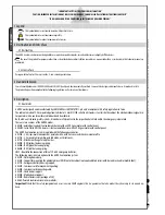
Page 4: ...balancing spring LB38 Board for the connection of three 12V 6Ah emergency batteries The following accessories are optional to the GARD 4 automation system G02801 Flashing dome lamp G02802 Support for mounting the photoelectric cell DIR onto the cabinet not applicable to barriers with bar and rack and or mobile foot G03751 Emergency battery housing support G02803 Luminous cord for movement signalli...

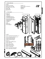
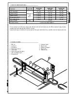
Page 5: ...r DIR photoelectric cells 8 G02803 Luminous cord 9 G02807 Fixed barrier support 10 G02808 Mobile barrier support 11 G02809 Adhesive reflector strips 12 G02801 Flashing dome lamp 13 G03751 Emergency battery housing support 14 G03753 Attachment flange for elyptical bar 11 VIEW FROMTHE BAR SUPPORT BRACKET VIEW FROM INSPECTION HATCH 1 Upper dome 2 Bar beam plate 3 Bar fitting intermediate plate 4 Cover...

Page 6: ... is necessary to Make sure the area selected for the mounting of the base and for the unit itself presents no hazards Provide for suitable omnipolar disconnection device with more than 3 mm between contacts to section power supply Connections inside the case made for protection circuit continuity are allowed as long as they include additional insulation with respect to other internal drive parts I...

Page 7: ...and distances 1 GARD unit 2 Control panel 3 Aluminium bar 4 Red phosphorescent strips 5 Luminous cord 6 Movement indicating flashing lamp 7 Column for photoelectric cells 8 Photoelectric cells 9 Fixed barrier support 10 Magnetic sensor 11 Photoelectric cell support 12 Magnetic reader 13 Column for reader 5 3 Cable list and minimun thickness 5 4 Standar installation Connections Type of cable Length...

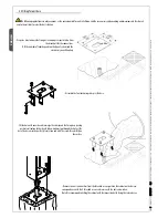
Page 8: ...ing clamps at the base Prepare a hole to house the fixing base and prepare sheath tubes from the branch pit for the connections N B the number of tubes depends on the type of system and the accessories you will hook up Remove the nuts and washers from the threaded screws position the cabinet on the base in correspondence with the 4 threaded screws and secure with the nuts and washers Note We recom...

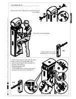
Page 9: ...t and turn it counter clockwise Should installation on the right be required the direction of the bar s opening must be inverted Proceed in the following manner remove the anchor bolt for springs from the transmission arm 1 release the gearmotor with the key turn the transmission arm around 2 secure the gearmotor again secure the anchor bolt to the transmission arm s opposite hole 3 invert the end...

Page 10: ...e bar cut the bar slot to the same length and insert it in the bar s conduit a procedure that should be carried out on both sides Insert the shock resistant profile and cut excess length Lastly secure the bar end plug with the screws provided Position the middle plate between the fitting plate and the bar fitting cover and put in one UNI 5931 M8x20 screw without tightening it to facilitate bar ass...

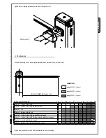
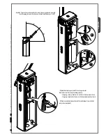
Page 11: ...nt profile and luminous cord Bare bar rack Bare bar luminous cord and rack Bare bar shock resistant profile and mobile barrier support Bare bar shock resistant profile luminous cord and mobile barrier support Bare bar rack and mobile barrier support Bare bar luminous cord rack and mobile barrier support Tighten the anti shearing protection cover to the bar fitting with screws 5 7 Bar balancing ByB...

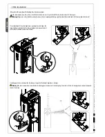
Page 12: ... installation manual are susceptible to change at any time and without obligation on CAME cancelli automatici s p a to notify users ENGLISH Release the gearmotor and position the bar vertically and then refasten the gearmotor Tighten the tie rod to the spring and then the top part of the spring to the anchor bolt with an anchor nut ...

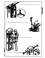
Page 13: ...k the tie rod to the anchoring bracket release the gearmotor and manually turn the spring to increase or decrease traction until the bar rests at 45 Tighten the blocking nut and refasten the gearmotor Note make sure the spring functions properly the spring is loose when the bar is in the vertical position at rest the spring is tight when the bar is in the horizontal position tense Perform any elec...

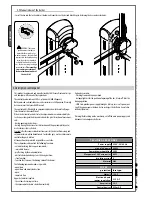
Page 14: ... spring system that activates the slowing down microswitch prior to the bar s total stop 5 8 End stop adjustment N B perform this procedure after finishing the electrical connections Close the door and power up the system activate the barrier to make sure it is parallel with the closed and at about 89 when open Warning For greater safety and better unit performance the bar s opening and closing ope...

Page 15: ...bligation on CAME cancelli automatici s p a to notify users ENGLISH After bar opening and closing adjustment tighten the locking nuts under the dampers reposition the inspection door and top crown Once you have completed all mechanical and electronic installation procedures secure the control panel cover Turn the key clock wise and lock the protective top cap using the Ø3 9x13 supplied with the pa...

Page 16: ...indicator obstacle detection when gate is still in any position slave function function that increases the braking action of the barrier The following command modes are possible open close open close and maintained action open complete stop Apposite trimmers regulate the automatic closing run time the amperometric device s detection sensitivity Optional accessories Flashing Crown and Luminous band...

Page 17: ...frequency card input see table page 19 7 SENSTrimmer adjusts amperometric sensitivity 8 TCATrimmer adjusts automatic closing time 9 Function selector Dip switch 10 Code storing button 11 Signalling LEDs for radio codes automatic closing 12 Adjustment connectors for deceleration speed 13 Connectors for LB38 battery charger 14 Command type selection jumper for button 2 7 15 Transformer 16 Power supp...

Page 18: ... to earth Stopbutton N C socket Bar stop button Excludes automatic closing For motion to resume press the com mand button or the remote control button Ifnotused setDips9toON Commandbutton N O contact Bar opening or closing button By pressing on the button the bar opens or inverts its movement depending on the selection made on Dipswitch 2 Check setting of the Jumper n 14 page 15 as per figure Openi...

Page 19: ...evices When bar leaves are closing opening the contact causes reversal until total opening is obtained Ifnotused shortcircuitcontact2 C1 DIRphotocells Safetydevices 6 3 Adjusting movement and deceleration speeds To adjsut the opening and closing speed move transformer faston labeled A to Velocità Min Med Max To adjsut the decelerations move the faston B to Rallentam Min Max Black White Red Openbar...

Page 20: ...e pag 16 5 ON Pre Opening and closing flasher Following and opening and closing command the flasher connected to 10 E flashes for 5 seconds before motion begins 6 ON Obstacle detected When motor is stopped bar closed or after a total stop command it prevents any movement if safety devices such as photocells detect any obstacles 7 ON Slave function Activate when two barriers are coupled see connecting...

Page 21: ...tenna s RG58 cable to the apposite terminals Antenna Lock the radiofrequency card into the electronic card AFTER CUTTING OFFTHE POWER SUPPLY or after disconnecting the batteries N B the electronic card only recognises the radiofrequency card when the power is on Radiofrequencycard Transmitters Seeinstructionsattachedto AF43SRradiofrequencycard Frequency MHz radiofrequency card Series of transmitte...

Page 22: ...Manual code 119GU55 119GU55 ver 0 2 0 2 03 2010 CAME cancelli automatici s p a The data and information reported in this installation manual are susceptible to change at any time and without obligation on CAME cancelli automatici s p a to notify users ENGLISH Radiofrequencyboard PROG Keep pressed the PROG button on the electronic card The LED will flash Press the button of transmitter to memorise T...

Page 23: ...e barrier 8 Connecting two coupled barriers to one command on the pre chosen Slave command card set Dipswitch 7 to ON perform power connection on termi nal L N connect the device to 10 E terminal output adjust to the same speed and deceleration as for the Master barrier On the pre chosen Master command card perform all the connections see electrical connections paragraph the installation procedure...

Page 24: ...vated by accident In the event of anomalous behaviour stop using the operator immediately Danger of crushing hands Danger High voltage No transit during operation Importantsafetyinstructions 10 Maintenance 10 1 Periodic maintenance Periodic maintenance to be carried out by the end user is as follows wipe clean the glass surface of the photocells check that the safety devices work properly remove a...

Page 25: ...elli automatici s p a The data and information reported in this installation manual are susceptible to change at any time and without obligation on CAME cancelli automatici s p a to notify users ENGLISH Periodicmaintenancelogforend user every6moths Date Notes Signature ...

Page 26: ...rator name Date of job Technician s signature Requester s signature Job performed ____________________________________________________________________________________________ _____________________________________________________________________________________________________ ___________________________________________________________________________________________ Installer s stamp Operator name...

Page 27: ...ed service companies for proper disposal Prior to disposal it is always advisable to check specific regulations in force in the place of disposal PLEASE DISPOSE OF PROPERLY 10 3 Problem solving MALFUNCTIONS REFERENCES CHECKS The unit neither opens nor shuts 1 2 3 4 6 8 18 1 Close the inspection hatch with the key and check the release lock The unit opens but does not close 4 7 10 2 Disable steady m...

Page 28: ...7 7860 Lessines Lessines 32 68 333014 32 68 338019 CHINA CAME Shanghai CAME Shanghai Automatic Gates Co Ltd Automatic Gates Co Ltd 1st Floor Bldg 2 No 1755 South Hongmei Road Shanghai Shanghai 200237 86 021 61255005 86 021 61255007 CAME Americas Automation Llc CAME Americas Automation Llc U S A 11405 NW 122nd St Medley Medley FL 33178 1 305 433 3307 1 305 396 3331 PORTUGAL CAME Portugal CAME Portu...

Reviews: