
A
ll t
h
e d
at
a a
n
d i
n
fo
rm
at
io
n c
o
n
ta
in
ed h
er
ei
n
i
s c
o
n
si
d
er
ed
s
u
b
je
ct to c
h
an
g
e a
t a
n
y t
im
e a
n
d a
t o
u
r d
is
cr
et
io
n
14
ENGLISH
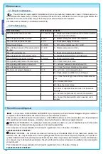
MALFUNCTIONS
REFERENCES
CHECKS
The unit neither opens nor shuts
1-2-3-4-6-8-20 1 - Chiudere sportello d’ispezione con la chiave e control-
lare la serratura dello sblocco
The unit opens but does not close
4-7-10
2 - Disable “steady movement” with dipswitch
The unit shuts but does not open
4-7-9
3 – Check power supply and fuses
No automatic closure
11-12-13
4 - N.C. safety contacts open (1-2 / 2-C1)
The unit does not work if the remote control
is used
2-14-16
6 - Disable master-slave function
The unit inverts direction
7
7 – Check spring tension and balancing
The unit works only with remote control
22
8 – Disable obstacle detection with dipswitch
The photoelectric cell does not react
12-23-24
9 – Check if end stop opens
The signalling LED indicator flashes rapidly
4
10 – Check if end stop closes
The signalling LED indicator remains on
13
11 - Activate “automatic closure” dip switch
The unit does not end its run
7
12 – Check the correct direction of movement
The bar is not properly balanced
7-15
13 - (2-3 / 2-4 / 2-7) command button
14 -Check jumper on AF43S, turn on/off power
15 – Check the bar length ratio with mountable accesso-
ries
16 – Re-save radio code
20 - Raise the motor torque
22 - Enter or duplicate the same code in all the remote
controls
23 - Activate the photoelectric cell with the dipswitch
24 - Connect the photoelectric cells in a series, not in
parallel
6.1 Periodic maintenance
The unit does not require specifi c maintenance. Only as a precautionary measure and in case of intensive use, we re-
commend periodic checks (every 6 months) on the state of the electric wire connected to the motor, the spring-bar balance, the
tightness of the nuts and the proper oiling of the sliding points between fi xed and mobile parts.
All checks must be recorded (in a dedicated record-book).
6 Maintenance
6.2 Problem solving
In its premises, CAME CANCELLI AUTOMATICI S.p.A. implements an Environmental Management System certifi ed in
compliance with the UNI EN ISO 14001 standard to ensure environmental protection.
Please continue our efforts to protect the environment—which CAME considers one of the cardinal elements in the development
of its operational and market strategies—simply by observing brief recommendations as regards disposal:
DISPOSAL OF PACKAGING – The packaging components (cardboard, plastic, etc.) are all classifi able as solid urban waste
products and may be disposed of easily, keeping in mind recycling possibilities.
Prior to disposal, it is always advisable to check specifi c regulations in force in the place of installation.
PLEASE DISPOSE OF PROPERLY!
PRODUCT DISPOSAL – Our products are made up of various types of materials. Most of them (aluminium, plastics, iron,
electrical wires, etc.) may be disposed of in normal garbage collection bins and can be recycled by disposing of in specifi c re-
cyclable material collection bins and disposal in authorized centres. Other components (electrical boards, remote control batteries,
etc.), however, may contain polluting substances. They should therefore be removed and given to qualifi ed service companies for
proper disposal.
Prior to disposal, it is always advisable to check specifi c regulations in force in the place of disposal.
PLEASE DISPOSE OF PROPERLY!
7 Demolition and disposal


