
A
ll t
h
e d
at
a a
n
d i
n
fo
rm
at
io
n c
o
n
ta
in
ed h
er
ei
n
i
s c
o
n
si
d
er
ed
s
u
b
je
ct to c
h
an
g
e a
t a
n
y t
im
e a
n
d a
t o
u
r d
is
cr
et
io
n
2
ENGLISH
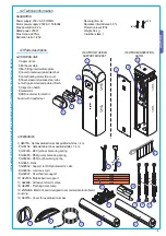
4.1 Gearmotor
GARD 4 was designed and manufactured by CAME CANCELLI AUTOMATICI S.p.A. and is compliant with safety regulations in
force. Guaranteed 24 months if not tampered with.
The cabinet is made of 2.5 mm painted galvanized steel or 2 mm AISI 304 satin-finish stainless steel. Inside the cabinet, the
electromechanical gearmotor operates with a container for electric board and transformer. Built with a anti-shearing safety
system, it includes a safety contact in the inspection hatch lock and in the emergency release lock.
There are two versions of the GARD 4 model:
G4041 - painted galvanized steel automatic barrier with a 24V DC gearmotor and container for board and transformer;
G4041I - satin-finish AISI 304 stainless steel automatic barrier with 24V DC gearmotor and container for board and transformer;
The GARD 4 automation system is supplied with the following accessories:
001 G03750 – L. 4m semioval aluminium bar, painted white, with slot cover and shock-resistant profi le;
001 G03752 – L. 4m oval aluminium bar, painted white, with slot cover;
001 G02040 – Ø 40 (yellow) balancing spring;
001 G04060 – Ø 50 (green) balancing spring;
001 G06080 – Ø 55 (red) balancing spring;
003 ZG5 – Plus electric board designed to accommodate radio board coupling;
003 ZG6 – Basic electric board designed to accommodate radio board coupling;
The following accessories are optional to the GARD 4 automation system:
002 RSE – Board for combined battery operation control and/or compass for ZG5 control board;
001 G02801 – Flashing dome lamp;
001 G02802 - Support for mounting the photoelectric cell (DIR) onto the cabinet (not applicable to barriers with bar and rack
and/or mobile foot);
001 G02803 - Luminous cord for movement signalling;
001 G02804 - Luminous cord connecting cable;
001 G02807 - Fixed barrier support;
001 G02808 – Mobile barrier support;
001 G02809 – Red reflector strips (package of 20);
001 G0465 – Painted aluminium rack in 2m modules;
Important! Check that the safety equipment and accessories are CAME originals; this is a guarantee that also makes the system
easy to set up and upkeep.
4 Description
2.1 Destination
1 Legenda simboli
This symbol indicates sections to be read with particular care.
This symbol indicates sections concernig safety
This symbol indicates notes to communicate to users.
The following standard were complied with for this product: EN 12978, UNI EN 954-1, CEI EN 60335-1, UNI EN 12453.
2 Destination and limits of use
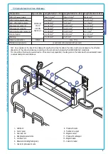
The GARD 4 automatic barrier was designed for use in private or public carparks, in residential areas or in highly traffi cked
areas.
The use of this product for purposes other than as described above and installation executed in a manner other than as
instructed in this technical manual are prohibited.
3 Standard followed
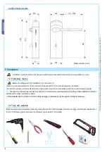
“IMPORTANT SAFETY INSTRUCTIONS FOR INSTALLATION”
“CAUTION: IMPROPER INSTALLATION MAY CAUSE SERIOUS DAMAGE, FOLLOW ALL INSTALLATION INSTRUCTIONS CAREFULLY”
“THIS MANUAL IS ONLY FOR PROFESSIONAL INSTALLERS OR QUALIFIED PERSONS”
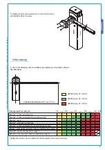
2.2 Limits of use
Passage width of up to 3.75 meters with a 4 second aperture time.


