background image

p.


10

 - M

anu

al 

FA0

158

1-

EN

 -

03

/2

02

1 - © C

AM

E Ö

ZA

K. - T

ra

ns

la

tio

n o

f t

he o

rig

in

al i

ns

tru

ct

io

ns - T

he c

on

te

nt

s o

f t

hi

s m

anu

al m

ay c

ha

ng

e, a

t a

ny t

ime

, a

nd wi

th

ou

t n

ot

ic

e.

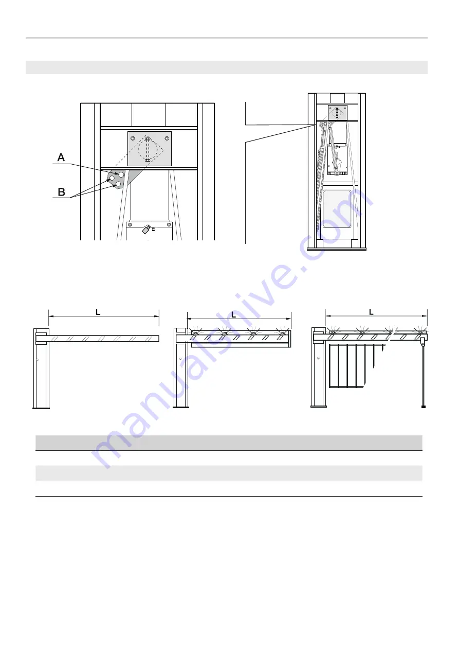
L = LATERAL CLEARANCE (m)

3 ÷ 4

4 ÷ 5

5 ÷ 6

6 ÷ 6.5

Boom

A

A

B

AB

Boom with the 001G0460 warning lights

A

B

AB

-

Boom with the 001G0465 warning lights and skirt or the 001G02808 swing leg

B

AB

BB

-

Boom with warning lights

Boom

Boom with warning lights and skirt 

or swing leg

BALANCING THE BOOM

The barrier is supplied with two Ø 50 mm springs (001G04060). The springs attach to lever arm (in the B-holes).

Depending on how the barrier is finally configured, you may need to exclude one of the two springs or reattach it (see the table below).

⚠ 

When configuring the barrier, make sure the gearmotor is locked!

⚠ 

WARNINGS!

The 001G02802 cannot be used on barriers fitted with the 001G0465 skirt or 001G02808 swing rest

The 001G02807 MUST be used with passage widths exceeding 3 m.

The 001G0465 and 001G02808 cannot be used together.


Summary of Contents for G6000T

Page 1: ...ZAK CAME COM OZAK Automatic barrier GARD series G6000T INSTALLATION MANUAL EN English FA01581 EN...

Page 2: ...2 1...

Page 3: ...must be explained to end users Fit in plain sight the machine s ID plate when the installation is complete All command and control devices must be installed at least 1 85 m from the boom s operating p...

Page 4: ...esidential areas or in high traffic volume areas Do not install of use this device in any way except as specified in this manual DIMENSIONS TECHNICAL DATA Model G6000T Protection rating IP 54 Power su...

Page 5: ...t 2 Anchoring plate 3 Motor shaft plate 4 Release lock 5 Gear motor 6 Balancing spring 7 Mechanical stops 8 Limit switch 9 Control panel 10 Adjustable transmission rod 11 Anchoring braces STANDARD INS...

Page 6: ...h 20 m 20 30 m Input voltage for 230 V AC control board 1P N PE 3G x 1 5 mm 2 3G x 2 5 mm 2 Command and control devices 2 x 0 5 mm 2 Signaling devices 2 x 0 5 mm 2 TX photocells 2 x 0 5 mm 2 RX photoc...

Page 7: ...the entry unit you will have to set up a cement slab Dig a hole for the foundation frame Set up the corrugated tubes needed for the wiring coming out of the junction pit The number of tubes depends o...

Page 8: ...st be done by at least two people During the initial mounting and fastening the barrier may be unstable and could tip over Then be careful to no rest against it until it is completely and securely fas...

Page 9: ...and the barrier anchor point and fasten it using the screws FASTENING THE BARRIER Place the cabinet onto the anchoring plate and fasten it using nuts and washers Internal zone Entry side Internal zone...

Page 10: ...warning lights and skirt or swing leg BALANCING THE BOOM The barrier is supplied with two 50 mm springs 001G04060 The springs attach to lever arm in the B holes Depending on how the barrier is finally...

Page 11: ...om should stabilize at 45 To precision balance the barrier first release the gear motor and loosen the rod nut Fit the nut to fasten the rod to the spring and tighten it Lock the gearmotor once again...

Page 12: ...rol board fuse 4 Motor fuse 5 Terminals for control and safety devices 6 AF card slot 7 SENS trimmer 8 ACT Trimmer 9 DIP SWITCH 10 Programming button 11 Programming warning LED 12 Speed and slow down...

Page 13: ...Closing micro switch Eyelet terminal with screw and washer for grounding connection Output to power 24 V AC accessories normally max 40 W If the power is out you can power up the 24 V DC accessories...

Page 14: ...he control device must be connected to 2 4 Set the jumper as shown in the figure OPEN ONLY function from control device with NO contact Warning in MAINTAINED ACTION mode the control device must be con...

Page 15: ...may change at any time and without notice Photocells Configure NC contact s C1 and or C5 input for safety accessories such as photocells C1 reopening while closing When the boom is closing opening the...

Page 16: ...the gear motor back into place ESTABLISHING THE LIMIT SWITCH POINTS Close the inspection hatch and power up the system Move the boom the check that it is parallel to the road surface when closed and...

Page 17: ...1 and 120 seconds DIP SWITCH Description of functions 1 ON AUTOMATIC CLOSING set 1 to OFF to deactivate it 2 ON ONLY OPEN from button 2 7 and or from transmitter with AF card fitted 2 OFF OPEN CLOSE...

Page 18: ...Programming LED AF card either AF43S or AF868 Programming LED PROG button Keep pressed the PROG programming button on the control board The programming LED flashes Press any key on the transmitter you...

Page 19: ...manual may change at any time and without notice ADJUSTING THE SPEED FINAL OPERATIONS Once you ve finished with the electrical connections and powered up the system replace the inspection hatch and lo...

Page 20: ...c a e l h e m r a e c i n 2 1 3 4 5 6 7 8 9 1 0 0 R a l l V e l 7 4 Z L 3 7 C O N T R O L P A N E L B A l i n e f u s e m o t o r f u s e a c c e s s o r i e s f u s e MASTER MASTER SLAVE p 20 Manual...

Page 21: ...arrier does not automatically close 11 12 13 6 Deactivate the MASTER SLAVE function The barrier does not work with the transmitter 2 14 16 7 Check the boom s balancing and spring tautness The boom s d...

Page 22: ...ls cardboard plastic and so on should be disposed of as solid household waste and simply separated from other waste for recycling Always make sure you comply with local laws before dismantling and dis...

Page 23: ...nie z za aczruklem VIIB De teclYllsche documentalie terzake s cpges1eld overeenstemm ng met de b jage VHB CAME S p a si unpegna a trasmettete f1 risposta a una richiesta adeguatamente motiva a de le a...

Page 24: ...caeli T rkiye T F 90 0 262 373 48 48 PBX ZAK CAME COM OZAK Manual FA01581 EN 03 2021 CAME ZAK Translation of the original instructions The contents of this manual may change at any time and without no...

Reviews: