


C
O
M
Rallen
tam.
Velocità
M
ax.
M
ax.
M
ed.
M
in.
M
in.
DIS. 27370
ON
2
1
3
4
5
6
7
8
9
10
N
M
PT
F
FC
FA
N
L
L27
L1T
E
+10
-11
1
2
3
5
7
C1
C5
GND
TX
RX
N
M
PT F FC FA
N
L
L2T
L1T
E +10 -11 1
2 3
5 7 C1 C5
GND
TX
RX
COM
NC
NC
COM
N
M
PT F FC FA
N
L
L2T
L1T
E +10 -11 1
2 3
5 7 C1 C5
GND
TX
RX
N
M
PT F FC FA
N
L
L2T
L1T
E +10 -11 1
2 3
5 7 C1 C5
GND
TX
RX
+ -
p.
13
- M
anu
al
FA0
158
1-
EN
-
03
/2
02
1 - © C
AM
E Ö
ZA
K. - T
ra
ns
la
tio
n o
f t
he o
rig
in
al i
ns
tru
ct
io
ns - T
he c
on
te
nt
s o
f t
hi
s m
anu
al m
ay c
ha
ng
e, a
t a
ny t
im
e, a
nd wi
th
ou
t n
ot
ic
e.
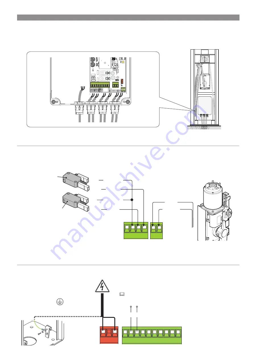
24 V DC gearmotor
Brown
Blue
Red
White
Orange
Orange
Opening micro
switch
Closing micro switch
Eyelet terminal with screw
and washer for grounding
connection.
Output to power 24 V AC accessories (normally) - max. 40 W.
If the power is out, you can power up the 24 V DC accessories by
using buffer batteries.
230 V AC - 50/60 Hz
POWER SUPPLY
FACTORY WIRING
The gearmotor is already connected.
To install the barrier on the right side, ask your local retailer for the documentation needed or contact Came
in your country, see www.came.com
ELECTRICAL CONNECTIONS
Connect all wires and cables in compliance with the law while using suitable cable glands, as shown in the drawing.
⚠
Use a cable gland only for the 230 V AC power supply cable.
⚠
The electrical cables must not touch any heated parts such as the motor, transformer, and so on.
Summary of Contents for G6000T
Page 2: ...2 1...


