


E +10 -11 1 2 3 5 7 C1 C5
L
N
RX TX GND
RX TX GND
L
N
E +10 -11 1 2 3 5 7 C1 C5
CAME
O
C
M
Max.
Med.
Min.
Min.
Max.
Velocità
Speed
Geschw.
Vitesse
Velocidad
Rallentamento
Deceleration
Geschw.
Ralentissement
D
Ab
e
n
c
a
el
h
e
m
ra
e
ción
2
1
3
4
5
6
7
8
9
10
0
Rall.
Vel.
7
4
ZL 37
CONTROL PANEL
"B"
"A"
line fuse
motor fuse
accessories fuse
CA
ME
O
C
M
Max.
Med.
Min.
Min.
Max.
Velocità
Speed
Geschw.
Vitesse
Velocidad
Rallentamento
Deceleration
Geschw.
Ralentissement
D
Ab
e
n
c
a
el
h
e
m
ra
e
ción
2
1
3 4 5 6 7 8 9 10
0
Rall.
Vel.
7
4
ZL 37
CONTROL PANEL
"B"
"A"
line fuse
motor fuse
accessories fuse
p.
21
- M
anu
al
FA0
158
1-
EN
-
03
/2
02
1 - © C
AM
E Ö
ZA
K. - T
ra
ns
la
tio
n o
f t
he o
rig
in
al i
ns
tru
ct
io
ns - T
he c
on
te
nt
s o
f t
hi
s m
anu
al m
ay c
ha
ng
e, a
t a
ny t
ime
, a
nd wi
th
ou
t n
ot
ic
e.
TROUBLESHOOTING
PROBLEM
REFERENCE
CHECK
The barrier neither opens nor closes
2-3-4-6-8-18
2 - Deactivate the MAINTAINED ACTION function
The boom opens but does not close
4-7-10
3 - Check the power supply and fuses
The boom closes but does not open
4-7-9
4 - The NC contacts are open
Thebarrier does not automatically close
11-12-13
6 - Deactivate the MASTER-SLAVE function
The barrier does not work with the transmitter 2-14-16
7 - Check the boom's balancing and spring tautness
The boom's direction of travel is inverted
7-18
8 - Deactivate the OBSTRUCTION DETECTION function
Only one transmitter works
22
9 - Check the opening limit-switch
The photocells do not work
12-23-24
10 - Check the closing limit-switch
The warning LED flashes quickly
4
11 - Activate the AUTOMATIC CLOSING function
The warning LED stays lit
13
12 - Check the proper direction of travel
The boom does not reach the limit-switch
7
13 - Check the control devices
The boom cannot be balanced
7-15
14 - Replace the AF card
The barrier does not slow down
7-15
15 - Check the length ration between boom and applied acces-
sories
The barrier does not work with emergency
batteries
8-25-26
16 - Memorize the radio code again
The boom starts slow
7
18 - Adjust the sensitivity
22 - Enter or duplicate the same code on all transmitters
23 - Activate the photocells
24 - Connect the photocells serially instead of in parallel fashion
25 - Check the batteries
26 - Respect the photocell's power supply polarities
Black
Red
Black
Red
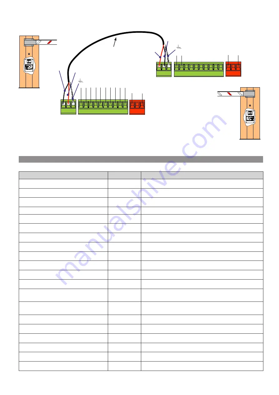
Screened cable
2402C 22AWG-type cables
Connect the two control boards using terminals RX-TX-GND as shown in the figure.
CONTROL BOARD
SLAVE
CONTROL BOARD
MASTER
Summary of Contents for G6000T
Page 2: ...2 1...


