


CAME
G6000T
p.
3
- M
anu
al
FA0
158
1-
EN
-
03
/2
02
1 - © C
AM
E Ö
ZA
K. - T
ra
ns
la
tio
n o
f t
he o
rig
in
al i
ns
tru
ct
io
ns - T
he c
on
te
nt
s o
f t
hi
s m
anu
al m
ay c
ha
ng
e, a
t a
ny t
ime
, a
nd wi
th
ou
t n
ot
ic
e.
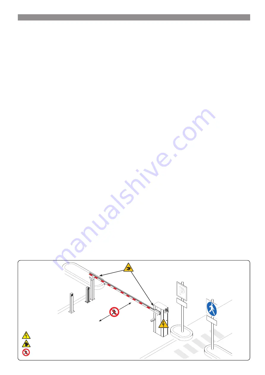
D
anger
of
high
voltage
D
anger
of
hanD
entrapment
D
o
not
enter
GENERAL PRECAUTIONS FOR INSTALLERS
⚠
CAUTION! Important safety instructions.
Follow all of these instructions. Improper installation can cause serious bodily harm.
Before continuing, also read the general precautions for users.
This product must only be used for its specifically intended purpose. Any other use is dangerous. ÖZAK is not liable for any damage caused by
improper, wrongful and unreasonable use. • This manual's product is defined by machinery directive 2006/42/CE as "partly-completed machinery".
Partly-completed machinery is a set that almost constitutes a machine, but which, alone, cannot ensure a clearly defined application. Partly-completed
machinery is only destined to be incorporated or assembled to other machinery or other partly-completed machinery or apparatuses to build machinery
that is regulated by Directive 2006/42/CE. The finalized installation must comply with European Directive 2006/42/CE and with currently applicable
European standards. • Given these considerations, all procedures stated in this manual must be exclusively performed by expert, qualified staff. • Laying
the cables, installation and testing must follow state-of-the-art procedures as dictated by regulations • make sure that the opening of the automatic
barrier does not constitute a hazard • do not install the operator onto surfaces that could yield and bend. If necessary, add suitable reinforcements to
the anchoring points • check that the temperature range appearing on the operator is suited to the place of installation • do not install on slopes, that is,
on any surfaces that are not perfectly level • check that no lawn watering devices spray the operator with water from the bottom up • Suitably section
off and demarcate the entire installation site to prevent unauthorized persons from entering the area, especially minors and children. • be careful when
handling operators that weigh over 20 kg. If need be, use proper safety hoisting equipment • Please use suitable protections to prevent any mechanical
hazards when people are moving around the machinery. • Any residual risks must be notified by proper, clearly visible pictograms, which must be
explained to end users • Fit, in plain sight, the machine's ID plate when the installation is complete • All command and control devices must be installed
at least 1.85 m from the boom's operating perimeter, or, where they are out of reach from outside the barrier • Unless the key-operation is functioning
(for e.g. keypad selector, key-switch selector, transponder selector, and so on), any maintained-action control devices must be installed at least 1.5 m
from the ground and out of reach from unauthorized users. • The manufacturer declines any liability for using non-original products; which would result
in warranty loss • All maintained-action switches must be fitted so as to be clearly visible from the boom's maneuvering area, and yet well away from
any moving parts • Affix a permanent tag, that describes how to use the manual release mechanism, close to the mechanism. • Before handing over to
users, check that the system is compliant with the 2006/42/CE uniformed Machinery Directive. Make sure the settings on the operator are all suitable
and that any safety and protection devices, and also the manual release, work properly. • If the power-supply cable is damaged, it must be immediately
replaced by the manufacturer or by an authorized technical assistance center, or in any case, by qualified staff, to prevent any risk • During all phases of
the installation make sure you have cut off the mains power source. • The electrical cables must run through the cable glands and must not touch any
heated parts, such as the motor, transformer, and so on). • Make sure you have set up a suitable dual pole cut off device along the power supply that
is compliant with the installation rules. It should completely cut off the power supply according to category III surcharge conditions. • When the passage
width clearance is greater than 3 m, you must use a fixed rest for the boom to support it • If the barrier is for both pedestrians and vehicles, you must
check that it is collision force compliant pursuant to standards EN12453 and EN12445 • If the barrier is only for vehicles, you must set up a suitable
pedestrian passage near the vehicle entry, and post suitable signage that prohibit transit of pedestrians and bicycles through the opening • Keep the
section of this manual inside the technical folder along with the manuals of all the other devices used for your automation system. Remember to hand
over to the end users all the operating manuals of the products that make up the final machinery.
- The figure shows which points constitute a potential hazard to people -
Summary of Contents for G6000T
Page 2: ...2 1...


