


3
4
8
1
6
7
10
2
9
5
11
CA
ME
1
10
5
6
8
7
4
2
11
9
3
5
p.
5
- M
anu
al
FA0
158
1-
EN
-
03
/2
02
1 - © C
AM
E Ö
ZA
K. - T
ra
ns
la
tio
n o
f t
he o
rig
in
al i
ns
tru
ct
io
ns - T
he c
on
te
nt
s o
f t
hi
s m
anu
al m
ay c
ha
ng
e, a
t a
ny t
ime
, a
nd wi
th
ou
t n
ot
ic
e.
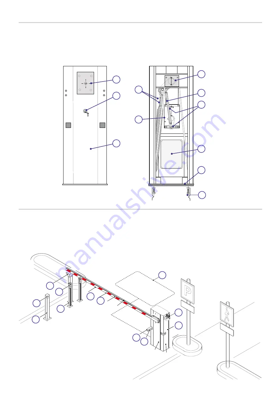
DESCRIPTION OF PARTS
1. Cabinet
2. Anchoring plate
3. Motor-shaft plate
4. Release lock
5. Gear motor
6. Balancing spring
7. Mechanical stops
8. Limit switch
9. Control panel
10. Adjustable transmission rod
11. Anchoring braces
STANDARD INSTALLATION
1. Barrier with boom
2. Flashing light
3. Warning lights
4. Reflective strips
5. Photocells
6. Photocell casing
7. Small photocell post
8. Fixed rest
9. Coil
10. Control device post
11. Control device (keypad selector, transponder sensor)
Summary of Contents for G6000T
Page 2: ...2 1...


