~1°
ENGLISH
P
age
1
4
1
4
- M
a
nu
a
l C
o
d
e:
1
1
9
G
V
2
2
1
1
9
G
V22 v
e
r.
2
.1
2
.1
1
2
/2
0
11 © C
A
M
E
c
a
n
ce
lli a
u
to
mati
ci
S
.p.
a
. - T
h
e d
a
ta a
n
d i
n
fo
rm
ati
o
n
i
n
thi
s ma
nu
a
l ma
y b
e c
h
a
n
g
e
d at a
n
y time a
n
d with
o
ut
o
b
lig
ati
o
n
o
n
the p
a
rt
of C
a
me C
a
n
ce
lli A
u
to
mati
ci
S
.p.
a
. to n
o
tify s
a
id
c
h
a
n
g
e
s.
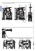
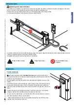
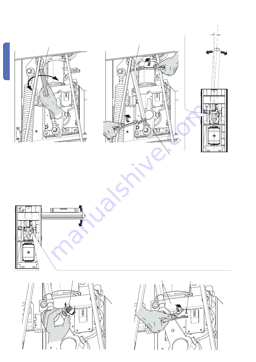
To correct the vertical positione (=opening), open the inspection hatch and turn the jointed arm either clockwise or coutnerclockwise,
then, secure the arm by using the nut, above and below.
To correct the horizontal positione (=closing), adjust the limit switch pin and secure it by tightening the screw found below the mechanical
stop.
Jointed arm
Limit switch pin
UNI 5739 6X20 screw
Mechanical stop
Nut M16
Nut M16
Summary of Contents for G6500
Page 29: ...B a r r i e r l i n e G6500 SERIES GARD INSTALLATION MANUAL STREET BARRIERS English EN 9 1...
Page 85: ...B a r r i e r l i n e G6500 GARD RU 9 RU...
Page 94: ...362 mm 10 10 119 G V 22 119 G V 22 2 1 2 1 12 2011 2011 CAME cancelli automatici s p a 6500...
Page 96: ...12 12 119 G V 22 119 G V 22 2 1 2 1 12 2011 2011 CAME cancelli automatici s p a...
Page 107: ...CA ME 2 3 2 3 119 G V 22 119 G V 22 2 1 2 1 12 2011 12 2011 CAME cancelli automatici s p a...
Page 111: ...27 27 119 G V 22 119 G V 22 2 1 2 1 12 2011 12 2011 CAME cancelli automatici s p a...

