%##
,
.
28 48 '.$
28 48 '.$
,
.
%##
SX
DX
%
#
#
'.$
48
28
.
-
04
&
&#
&!
.
,
,
,4
/.
'.$
48
28
%
#
#
.
-
04
&
&#
&!
.
,
,
,4
/.
ENGLISH
P
age
2
2
2
2
- M
a
nu
a
l C
o
d
e:
1
1
9
G
V
2
2
1
1
9
G
V22 v
e
r.
2
.1
2
.1
1
2
/2
0
11 © C
A
M
E
c
a
n
ce
lli a
u
to
mati
ci
S
.p.
a
. - T
h
e d
a
ta a
n
d i
n
fo
rm
ati
o
n
i
n
thi
s ma
nu
a
l ma
y b
e c
h
a
n
g
e
d at a
n
y time a
n
d with
o
ut
o
b
lig
ati
o
n
o
n
the p
a
rt
of C
a
me C
a
n
ce
lli A
u
to
mati
ci
S
.p.
a
. to n
o
tify s
a
id
c
h
a
n
g
e
s.
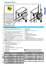
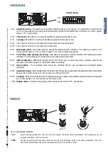
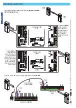
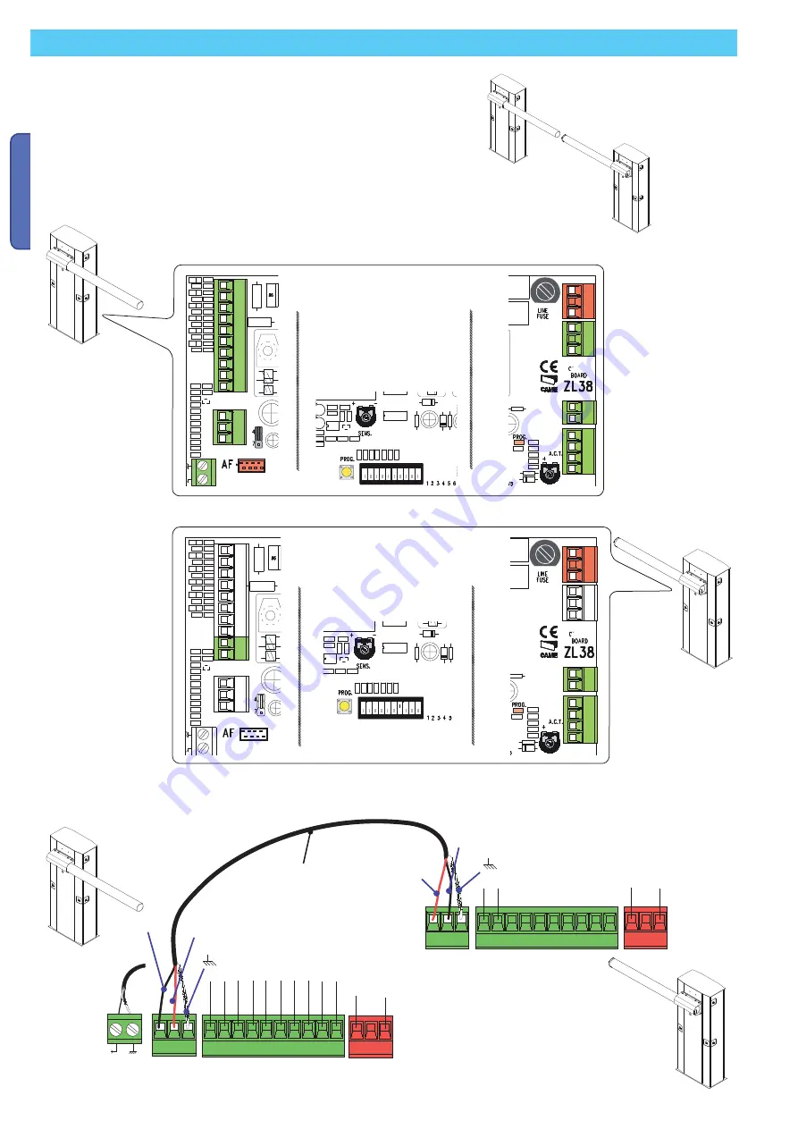
7 ON
COMMAND CARD
MASTER
COMMAND CARD
SLAVE
Black
Red
Black
Red
Screened cable
2402C 22AWG
COMMAND CARD
MA-
STER
COMMAND CARD
SLAVE
Connecting two coupled barriers
You need to determine which barrier will be the
Master and which
the
Slave
because
because:
- on barrier
Slave
only
connect the main
power (terminals L-N)
and any pertinentn
warning devices (termi-
nals 10-E); also, set Dip
switch 7 to ON, adjust
the travel and decele-
ration speeds as on the
Master barrier.
- sulla barriera
Master
perform all connec-
tions, settings and
adjustments needed
for the installation;
also, activate the
remote control on this
barrier.
At the end, connect the two cards together using the terminals
RX-TX-GND
.
Summary of Contents for G6500
Page 29: ...B a r r i e r l i n e G6500 SERIES GARD INSTALLATION MANUAL STREET BARRIERS English EN 9 1...
Page 85: ...B a r r i e r l i n e G6500 GARD RU 9 RU...
Page 94: ...362 mm 10 10 119 G V 22 119 G V 22 2 1 2 1 12 2011 2011 CAME cancelli automatici s p a 6500...
Page 96: ...12 12 119 G V 22 119 G V 22 2 1 2 1 12 2011 2011 CAME cancelli automatici s p a...
Page 107: ...CA ME 2 3 2 3 119 G V 22 119 G V 22 2 1 2 1 12 2011 12 2011 CAME cancelli automatici s p a...
Page 111: ...27 27 119 G V 22 119 G V 22 2 1 2 1 12 2011 12 2011 CAME cancelli automatici s p a...

