Page
18
- Manual
FA01626-EN
- 02/2023 - © C
AME S.p.A. - The contents of this manual may be changed at any time and without notice. - T
ranslation of the o
riginal instructions
ELECTRICAL CONNECTIONS
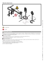
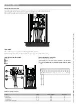
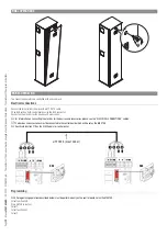
Passing the electrical cables
The electrical cables must not touch any parts that may overheat during use (such as the motor and transformer).
Make sure that the moving mechanical parts are suitably far away from the wiring.
Power supply
Make sure the mains power supply is disconnected during all installation procedures.
Before working on the control panel, disconnect the mains power supply and remove the batteries, if any.
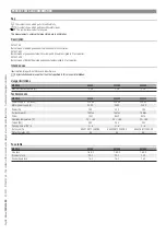
Connecting to the electrical network
F
Line fuse
L
Phase
N
Neutral
Earth
F
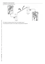
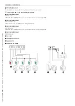
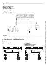
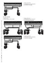
Power supply output for accessories
The output normally delivers 24 V AC.
The output delivers 24 V DC when the batteries start operating, if they are installed.
The sum of the power draw for the connected accessories must not exceed
40 W.
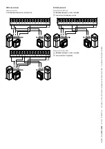
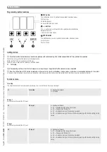
10 11 E1 E6 Rx Tx 1
2
3 3P 4
5
7
CY
CX
E1 E6 Rx Tx 1
2
3 3P 4
5
7
CY
CX
Maximum capacity of contacts
Device
Output
Power supply (V)
Power (W)
Accessories
10 - 11
24 AC
40
Additional light
10 - E1
24 AC
25
Flashing beacon
10 - E1
24 AC
25
Operator status warning light
10 - 5
24 AC
3

