


page
3
- Manual
FA01260-IT
- 10/2018 - © CAME S.p.A. - The contents of this manual may be changed, at any time, and without notice
. - T
ranslation of the original instructions
D
ANGER
OF
HIGH
VOLTAGE
D
ANGER
OF
HAND
ENTRAPMENT
D
O
NOT
ENTER
GENERAL PRECAUTIONS FOR INSTALLERS
⚠
CAUTION! Important safety instructions.
Follow all of these instructions. Improper installation can cause serious bodily harm.
Before continuing, also read the general precautions for users.
T
HIS
PRODUCT
MUST
ONLY
BE
USED
FOR
ITS
SPECIFICALLY
INTENDED
PURPOSE
. A
NY
OTHER
USE
IS
DANGEROUS
. C
AME
S.P.A.
IS
NOT
LIABLE
FOR
ANY
DAMAGE
CAUSED
BY
IMPROPER
,
WRONGFUL
AND
UNREASONABLE
USE
. • T
HIS
MANUAL
'
S
PRODUCT
IS
DEFINED
BY
THE
M
ACHINERY
D
IRECTIVE
2006/42/CE
AS
PARTLY
-
COMPLETED
MACHINERY
. P
ARTLY
-
COMPLETED
MACHINERY
IS
AN
ASSEMBLY
THAT
ALMOST
CONSTITUTES
A
MACHINE
,
BUT
WHICH
,
ALONE
,
CANNOT
ENSURE
A
CLEARLY
DEFINED
APPLICATION
. P
ARTLY
-
COMPLETED
MACHINERY
IS
ONLY
DESTINED
TO
BE
INCORPORATED
OR
ASSEMBLED
TO
OTHER
MACHINERY
OR
OTHER
PARTLY
-
COMPLETED
MACHINERY
OR
APPARATUSES
TO
BUILD
MACHINERY
THAT
IS
REGULATED
BY
D
IRECTIVE
2006/42/CE. T
HE
FINAL
INSTALLATION
MUST
BE
COMPLIANT
WITH
E
UROPEAN
DIRECTIVE
2006/42/CE
AND
E
UROPEAN
REFERENCE
STANDARDS
: EN 13241-1, EN 12453, EN 12445
AND
EN 12635. • B
Y
VIRTUE
OF
THESE
CONSIDERATIONS
,
ALL
THE
PROCEDURES
MENTIONED
IN
THIS
MANUAL
MUST
BE
CARRIED
OUT
ONLY
BY
SKILLED
AND
QUALIFIED
PERSONNEL
• L
AYING
OF
CABLES
,
INSTALLATION
AND
TESTING
MUST
FOLLOW
STATE
-
OF
-
THE
-
ART
PROCEDURES
AS
DICTATED
BY
APPLICABLE
STANDARDS
AND
LAWS
•
MAKE
SURE
THAT
THE
AUTOMATIC
BARRIER
OPENING
DOES
NOT
CAUSE
DANGEROUS
SITUATIONS
• D
O
NOT
INSTALL
THE
OPERATOR
OR
ONTO
ELEMENTS
THAT
COULD
BEND
. I
F
NECESSARY
,
ADD
SUITABLE
REINFORCEMENTS
TO
THE
ANCHORING
POINTS
• C
HECK
THAT
THE
TEMPERATURE
RANGES
GIVEN
AND
THOSE
OF
THE
LOCATION
MATCH
• D
O
NOT
INSTALL
IN
PLACES
UPHILL
OR
DOWNHILL
(
I
.
E
.
THAT
ARE
NOT
LEVEL
) • C
HECK
THAT
NO
LAWN
WATERING
DEVICES
SPRAY
THE
OPERATOR
WITH
WATER
FROM
THE
BOTTOM
UP
• D
EMARCATE
THE
ENTIRE
SITE
TO
PREVENT
UNAUTHORIZED
PERSONNEL
TO
ENTER
;
ESPECIALLY
CHILDREN
AND
MINORS
• B
E
CAREFUL
WHEN
HANDLING
OPERATORS
WEIGHING
MORE
THAN
20
KG
. I
F
NECESSARY
USE
DEVICES
FOR
SAFE
HANDLING
• U
SE
SUITABLE
PROTECTIONS
TO
PREVENT
ANY
MECHANICAL
HAZARDS
DUE
TO
PERSONS
LOITERING
WITHIN
THE
OPERATING
RANGE
OF
THE
MACHINERY
.• A
NY
RESIDUAL
RISKS
MUST
BE
INDICATED
CLEARLY
WITH
PROPER
SIGNAGE
AFFIXED
IN
VISIBLE
AREAS
. A
LL
OF
WHICH
MUST
BE
EXPLAINED
TO
END
USERS
• F
IT
,
IN
PLAIN
SIGHT
,
THE
MACHINE
'
S
ID
PLATE
WHEN
THE
INSTALLATION
IS
COMPLETE
. • A
LL
COMMAND
AND
CONTROL
DEVICES
MUST
BE
INSTALLED
AT
LEAST
1.85
M
FROM
THE
PERIMETER
OF
THE
BOOM
MOVEMENT
AREA
OR
WHERE
THEY
CANNOT
BE
REACHED
FROM
THE
OUTSIDE
THROUGH
THE
BARRIER
• U
NLESS
THE
KEY
OPERATION
(
E
.
G
.
KEYBOARD
SELECTOR
,
KEY
SELECTOR
,
TRANSPONDER
SELECTOR
SWITCH
,
ETC
.)
IS
PROVIDED
,
THE
HOLD
-
TO
-
RUN
CONTROL
DEVICES
MUST
BE
INSTALLED
AT
A
HEIGHT
OF
AT
LEAST
1.5
M
IN
A
PLACE
NOT
ACCESSIBLE
TO
THE
PUBLIC
• T
HE
MANUFACTURER
DECLINES
ANY
LIABILITY
FOR
USING
NON
-
ORIGINAL
PRODUCTS
;
WHICH
WOULD
RESULT
IN
WARRANTY
LOSS
• A
LL
SWITCHES
IN
HOLD
-
TO
-
RUN
MODE
MUST
BE
POSITIONED
IN
PLACES
FROM
WHICH
THE
BOOM
MANOEUVRING
AREA
IS
COMPLETELY
VISIBLE
,
YET
AWAY
FROM
MOVING
PARTS
• A
PPLY
A
PERMANENT
LABEL
DESCRIBING
HOW
TO
USE
THE
MANUAL
RELEASE
MECHANISM
NEAR
THE
RELATIVE
DRIVE
ELEMENT
• B
EFORE
HANDING
OVER
TO
USERS
,
CHECK
THAT
THE
SYSTEM
IS
COMPLIANT
WITH
THE
2006/42/CE
UNIFORMED
M
ACHINERY
D
IRECTIVE
. M
AKE
SURE
THAT
THE
OPERATOR
HAS
BEEN
PROPERLY
ADJUSTED
AND
THAT
THE
SAFETY
AND
PROTECTION
DEVICES
,
AND
THE
MANUAL
RELEASE
,
ARE
WORKING
PROPERLY
• I
F
THE
POWER
-
SUPPLY
CABLE
IS
DAMAGED
,
IT
MUST
BE
IMMEDIATELY
REPLACED
BY
THE
MANUFACTURER
OR
BY
AN
AUTHORIZED
TECHNICAL
ASSISTANCE
CENTER
,
OR
IN
ANY
CASE
,
BY
QUALIFIED
STAFF
,
TO
PREVENT
ANY
RISK
• M
AKE
SURE
THE
MAINS
POWER
SUPPLY
IS
DISCONNECTED
DURING
ALL
INSTALLATION
PROCEDURES
• T
HE
ELECTRICAL
CABLES
MUST
RUN
THROUGH
THE
CABLE
GLANDS
AND
NOT
TOUCH
ANY
PARTS
THAT
MAY
OVERHEAT
,
SUCH
AS
THE
MOTOR
,
TRANSFORMER
,
AND
SO
ON
. • M
AKE
SURE
YOU
HAVE
SET
UP
A
SUITABLE
DUAL
POLE
CUT
OFF
DEVICE
ALONG
THE
POWER
SUPPLY
THAT
IS
COMPLIANT
WITH
THE
INSTALLATION
RULES
. I
T
SHOULD
COMPLETELY
CUT
OFF
THE
POWER
SUPPLY
ACCORDING
TO
CATEGORY
III
SURCHARGE
CONDITIONS
• W
HEN
THE
WIDTH
OF
PASSAGE
IS
MORE
THAN
3
M
,
IT
IS
MANDATORY
TO
USE
A
FIXED
SUPPORT
FOR
THE
BOOM
TO
SUPPORT
IT
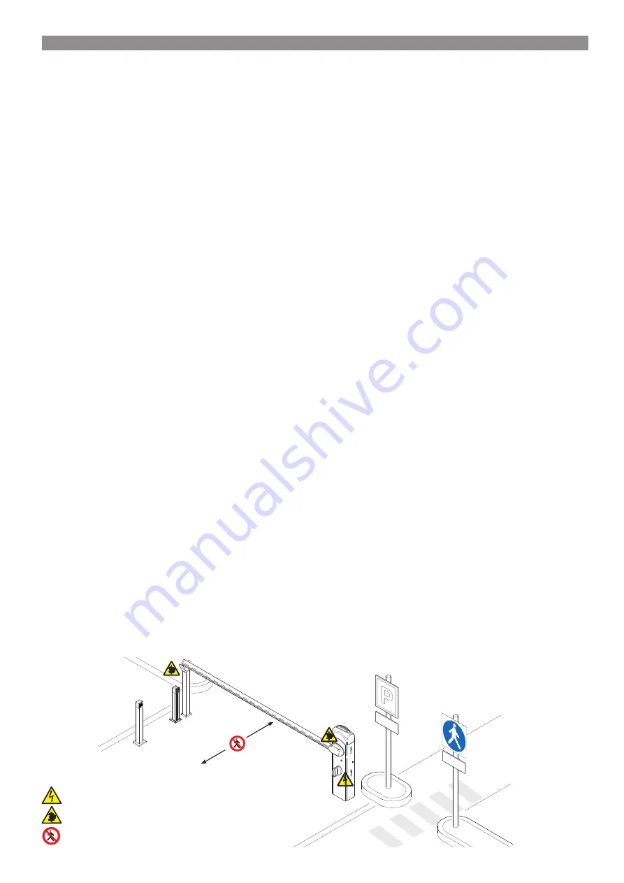
• I
F
THE
BARRIER
IS
FOR
MIXED
USE
(
VEHICLES
AND
PEDESTRIANS
),
IT
IS
MANDATORY
TO
CHECK
THE
COMPLIANCE
OF
THE
IMPACT
FORCE
ACCORDING
TO
EN 12453
AND
EN 12445 • I
F
THE
BARRIER
IS
EXCLUSIVELY
FOR
VEHICLE
USE
,
IT
IS
NECESSARY
TO
PROVIDE
A
PEDESTRIAN
CROSSING
IN
THE
IMMEDIATE
VICINITY
OF
THE
VEHICLE
PASSAGE
,
AND
INDICATE
,
THROUGH
APPROPRIATE
SIGNS
,
THE
ABSOLUTE
PROHIBITION
OF
TRANSIT
TO
PEDESTRIANS
AND
BICYCLES
THROUGH
THE
GATE
• K
EEP
THE
SECTION
OF
THIS
MANUAL
RELATED
TO
INSTALLATION
INSIDE
THE
TECHNICAL
FOLDER
ALONG
WITH
THE
MANUALS
OF
ALL
THE
OTHER
DEVICES
USED
FOR
YOUR
OPERATOR
SYSTEM
R
EMEMBER
TO
HAND
OVER
TO
THE
END
USERS
ALL
THE
OPERATING
MANUALS
OF
THE
PRODUCTS
THAT
MAKE
UP
THE
FINAL
MACHINERY
.
-
The next fi gure shows the main hazard points for people
-
Summary of Contents for I1PB0500026
Page 2: ...4 4...


