


page
6
- Manual
FA01260-IT
- 10/2018 - © CAME S.p.A. - The contents of this manual may be changed, at any time, and without notice
. - T
ranslation of the original instructions
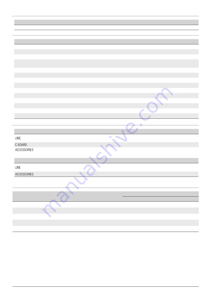
Fuse table
FUSES
ZL39
- Line
3.15 A-F = 120 V
1.6 A-F = 230 V
- Card
1 A-F
- Accessories
2 A-F
FUSES
IO-RS485
- Line
200 mA
- Accessories
200 mA
Technical data
Type
I1PB0500026 - I1PB0500027 - I1PB0500028
Protection rating (IP)
54 series
Power supply (V - 50/60 Hz)
230 AC
Motor power supply (V)
24 DC
Max draw (A)
15 (24 V)
1.3 (230 V)
Stand-by consumption (W)
8 series
Consumption with Sleep Mode (W)
5 series
Power (W)
300 series
Torque (Nm)
600 series
Opening time at 90° (s)
2 to 6
Duty cycle
CONTINUOUS SERVICES
Operating temperature (°C)
-20 to +55
Reduction ratio (i)
1/202
Insulation class
I
Weight (kg)
55 series
Limits to use
Type
I1PB0500026 - I1PB0500027 - I1PB0500028
Maximum clearance width of the passage (m)
4 series
Cable types and minimum thicknesses
Connection
cable length
< 20 m
20 < 30 m
Input voltage for 230 V AC control board (1P+N+PE)
3G x 1.5 mm
2
3G x 2.5 mm
2
Flashing light
2 x 0.5 mm
2
Command and control devices
2 x 0.5 mm
2
TX Photocells
2 x 0.5 mm
2
RX photocells
4 x 0.5 mm
2
When operating at 230 V and outdoors, use H05RN-F-type cables that are 60245 IEC 57 (IEC) compliant; whereas indoors,
use H05VV-F-type
cables that are 60227 IEC 53 (IEC) compliant. For power supplies up to 48 V, you can use FROR 20-22 II-type cables that
comply with EN 50267-2-1 (CEI).
To connect the antenna, use the RG58 (we suggest up to 5 m).
For combined connection and CRP, use a UTP CAT5-type cable (up to 1,000 m long).
If cable lengths differ from those specified in the table, establish the cable sections depending on the actual power draw of the
connected devic
es and according to the provisions of regulation CEI EN 60204-1.
F
or multiple, sequential loads along the same line, the dimensions on the table need to be recalculated according to the actual power draw
and distances. For connecting products that are not contemplated in this manual, see the literature accompanying said products
Summary of Contents for I1PB0500026
Page 2: ...4 4...


