p.
66
- M
an
u
al
fo
r
th
e
F
A
0
0
0
6
7
-E
N
fo
r th
e F
A
0
0
0
6
7
-E
N
v.
11
- 0
5
/2
0
15 - © C
am
e S
.p.
A
. - T
h
e m
an
u
al
's c
onte
nt
s m
ay b
e e
d
ite
d at a
ny ti
m
e w
ith
ou
t n
oti
ce
.
Legend
Parts to read carefully.
⚠
Parts about safety.
☞
What to tell users.
REFERENCE REGULATIONS
Came S.p.A. is certified for the: ISO 9001 quality and ISO
14001 environmental management systems.
This product complies with the current regulations
mentioned in the declaration of conformity.
DESCRIPTION
Four channel rolling code 433.92 or 868.35 MHz
transmitter for memorizing up to 500 transmitters
complete with one AT04 MASTER transmitter, with display
and Memory Roll card.
The system can be programmed and managed by using the
specific software (which can be requested) and a PC.
Limits to use
The minimum distance between receivers is 5 meters.
The antenna should be placed as high above the ground
as possible and as far from any metal or reinforced
concrete as possible.
Dimensions (mm)
Technical data
Type
Protection rating (IP)
54
Power supply (V)
12 - 24 AC - DC
Power draw when idle (mA)
100
Power (W)
1.5
Insulation class
Casing material
ABS
Operating temperature (°C)
-20 ÷ +55
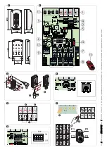
Description of parts
1. Display
2. FUNCTIONS select Dip switch
3. Relay timer trimmer OUT 2
4. Reset
button
5. Memory Roll card connector
6. RS232 connector for connecting to the PC
7. Antenna connection terminals
8. Device connection terminals (
*
)
9. Power supply terminals (
**
)
10. AF card connector
11. Programming buttons
12. 250 mA fuse
13. MASTER transmitter
(
*
) Operators and/or accessories to control:
OUT1 in monostable or bistable mode.
OUT2 in monostable mode with timer adjustable from
between 1 and 300 seconds.
OUT3 and OUT4 in monostable mode.
(
**
) Cable type: FROR CEI 20-22 CEI EN 50267-2-1, 2 x 1 mm
2.
INSTALLATION
⚠
Any installation and/or use other than that specified in
this manual is forbidden.
Fasten the receiver's base to an impact protected area
using suitable tools and equipment.
❶
.
Carefully perforate the pre-drilled Ø 20 mm holes
❷
. Fit
the cable glands with the corrugated tubes for threading
the electrical cables
❸
.
DISPLAY MESSAGES
Views the memory position of a transmitter.
During programming/maintenance operations, the
associated OUT outputs are shown. At normal working
conditions it indicates either the transmitter's channel
/ key. When it flashes it means that no transmitter is
memorized on that particular output.
If the dots flash, the transmitter in that memory position
is a MASTER transmitter.
☞
The default position of the MASTER transmitter is 001.
With this transmitter you can do all programming editing or
restoring operations.
☞
Keep the MASTER transmitter with the Memory Roll card.
PROGRAMMING
The following illustrations are merely examples.
Functions
DIP switches 1-2
Programming and maintenance
DIP switch 3 ON
Bistable relay on OUT 1
DIP switch 3 OFF
Monostable relay on OUT 1
DIP switch 4 OFF
Not used
Trimmer adjustments
OUT TIME:
Adjusting OUT2 timer between 1 and 300 seconds.
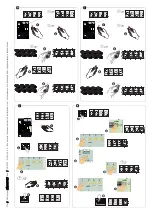
MEMORIZING THE FIRST TRANSMITTER (MASTER)
The first memorized transmitter will be the MASTER. This
transmitter enables you to perform all programming editing
or restoring operations.
☞
Keep the MASTER transmitter with the Memory Roll card.
Press key 1: the display will read Sto 1.
Press and keep pressed any key on the MASTER transmitter:
the wording will disappear on the receiver's screen.
Repeat
❶
and
❷
for each of the receiver keys and
corresponding Master transmitter KEYS: buttons 2, 3 and 4
with, keys P2, P3 e P4.


