SERIE
RODEO
14
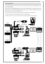
ZP8 ELECTRICAL CABINET
10
11
1
2
C1
Ri
M
R2
R1
2
F1 F2 ES ES
TX RX GND
1 2 3 4 5 6 7
MF9011 - MF9111
MA7032
1 2 3 4 5 6 7 8
2
1
3
4
5
6
7
8
9 10
O
N
2
1
3
4
O
N
RESET
APRE
MA7012
BUSSOLA
MA7041
P.R.AP
AP/PARZ
TCA
V.RALL.CH V/CH
V/AP
P.R.CH
FRENO V.RALL.AP.
FUSIBILE
ACCESSORI
1,6A
-
+
M
N
E
+
S
S
E
-
-
BATT.
+
24AC
24AC
TERMINAL
BOARD
FOR
CONNECTION
OF
ACCESSORIES
TERMINAL
BOARD
FOR
CONNECTION
OF
MOTOR
-
ENCODER
-
BATTERY
-
POWER
SUPPLY
24V
INDICATOR
LEDS
RAPID
-
BLOW
1.6A
FUSE
ON
ACCESSORIES
RESET
KEY
DIP
-
SWITCHES
ADJUSTMENT
TRIMMERS
SEAT
FOR
PHOTOCELL
CARD
MF
9011-9111
SEAT
FOR
EMERGENCY
OPERATION
CARD
MA
7032
CONNECTION
FOR
ELECTRIC
LOCK
MA7012
CONNECTION
FOR
"
COMPASS
"
OPERATING
SYSTEM
CONNECTION
FOR
FUNCTION
SWITCH
MA7041
OPEN
KEY
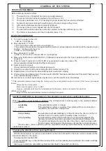
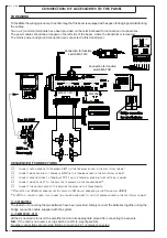
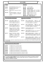
TERMINAL BOARD FOR CONNECTION OF ACCESSORIES
10 - 11 24V a.c./d.c. power to accessories
1 - 2
Pushbutton Stop, normally close contact (N.C.)
2 - C1 Photocells, re-opening during closing (N.C.)
2 - Ri
Normally open contact (N.O.) for central sensor (used only
when interface system is installed)
2 - R1 Normally open contact (N.O.) external sensor (can be excluded)
2 - R2 Normally open contact (N.O.) internal sensor
2 - M
Normally open contact (N.O.), for "step-by-step" operation
(manual button)
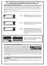
- Contact 1-2 and 2-C1 are normally closed (N.C.) and bridged together at the factory. To use these functions, replace
the bridge connections with the relative devices.
- The 2-C1 contact is used when a security system is desired (for example, photoelectric cells or other control
devices), which is not capable of being housed in the special clip-in seat. Note: if the MA9011/9111 photoelectric cell
card is not enabled, or if it is enabled and you wish to disable it, set dip switch 3 to ON (4-way module).
- The 2-M contact is normally open (N.O.), and has a double function:
1) During normal functioning it is enabled for opening, even if the MA7041 function selector is set on “doors closed”.
This function can be used for preferential passage, (e.g., evening closure, opening command on key or magnetic
switches).
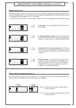
2) By setting dip switch 5 to ON (10-way module), the “stepper” opening function is enabled (by pressing the button
the door opens; pressing it again closes the door). Attention, by using this function contacts 2-R1 and 2-R2 are
excluded.
10
11
1
2
C1
Ri
M
R2
R1
2
F1 F2 ES ES
MA7012
P.R.AP
-
+
+
-
POWER SUPPLY CONNECTION TERMINAL BOARD
24V
Reduction gear power supply (supplied standard)
Earth connection
230V Power supply (50/60 Hz)
Line fuse 2A
(see page 22)
230V
24V


