21
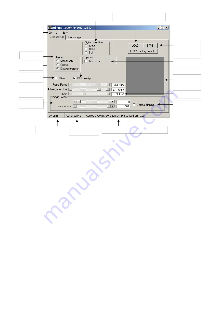
Figure 3-3: Windows based control application with options –DFG, -12 bit, -Delayed Transfer
Set
communications
preference
Readout mode
CC1 signal
polarity
Normal or
mirrored
Readout frame
period and
Integration time
Partial scan
control
Communication state
Communication
per Camera Link
Camera type, serial number and build state
Binning control
Set digital gain
Indication of
readout area of
CCD
Switch test pattern
on or off
Save current
settings as Power-
up default
settings
Load power-up defaults
Set output resolution
Summary of Contents for ADIMEC-1000m
Page 1: ...ADIMEC 1000m O p e r a t i n g a n d T e c h n i c a l M a n u a l ...
Page 2: ......
Page 6: ......
Page 10: ......
Page 12: ......
Page 16: ...14 Figure 2 1 4 crosshead screws that hold the lensmount front view of the camera ...
Page 18: ...16 ...
Page 39: ...37 Figure 4 2 Test Image ...
Page 41: ...39 Testpattern videolevels 12 bit ...
Page 48: ......
Page 56: ...54 ...
Page 60: ......
Page 62: ......
Page 67: ...65 10 MECHANICAL OUTLINE DRAWING Figure 10 1 Mechanical Outline drawing ...


