55
7. COMMUNICATION PROTOCOL
By using the console application you can type commands that are immediately send to the camera. The console
application can be found on the floppy disk included with the delivery in the directory A:\Control\Console. It is useful
if you want to write your own dedicated application to get acquainted with the commands and the return messages.
The camera is controlled by a host system connected to the Camera Link interface using the serial communication link
of the Camera Link. Commands and resulting data are transferred between the host system and the camera
according a communication protocol. The host system is master in the communication link. All actions are initiated by
the host system. The camera only replies on messages received from the host system.
The correct COM-Port should be set in the console.ini file.
7.1 Data link settings
The data link settings that shall be used for communication with the Adimec-1000m camera are:
Baudrate 57600
baud
Stop bit
1
Data bit
8
Parity
none
Handshaking none
7.2 Data flow characters
The communication protocol uses data flow control characters to identify a message and for acknowledgement.
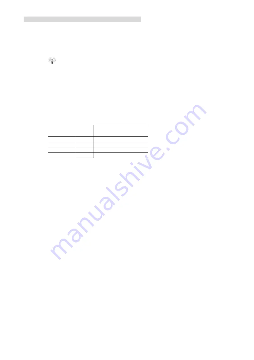
The following data flow characters are defined:
Character Dec Description
NUL
0
NUL character, is ignored
STX
64
start of message identifier
ETX
13
end of message identifier
ACK 6
positive
acknowledgement
NAK 21
negative
acknowledgement
Summary of Contents for ADIMEC-1000m
Page 1: ...ADIMEC 1000m O p e r a t i n g a n d T e c h n i c a l M a n u a l ...
Page 2: ......
Page 6: ......
Page 10: ......
Page 12: ......
Page 16: ...14 Figure 2 1 4 crosshead screws that hold the lensmount front view of the camera ...
Page 18: ...16 ...
Page 39: ...37 Figure 4 2 Test Image ...
Page 41: ...39 Testpattern videolevels 12 bit ...
Page 48: ......
Page 56: ...54 ...
Page 60: ......
Page 62: ......
Page 67: ...65 10 MECHANICAL OUTLINE DRAWING Figure 10 1 Mechanical Outline drawing ...


