61
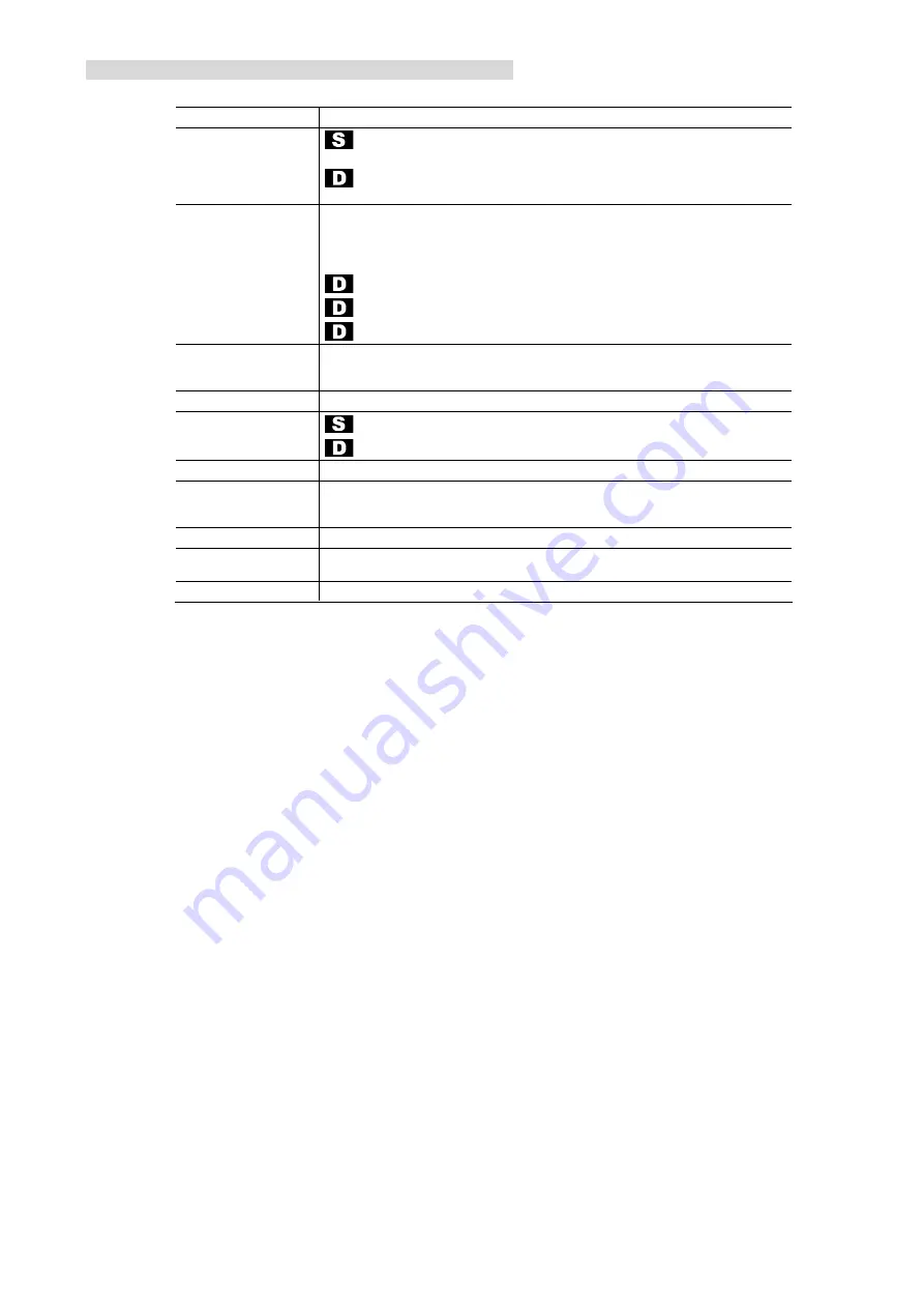
9. TECHNICAL SPECIFICATION SUMMARY
All performance parameters are typical.
CCD sensor
7.4
µ
m pixels, Interline transfer with micro lenses.
Video output
: 1 channel digital video via Camera Link, 40 MHz pixel clock. 8 bit, 10 bit or
12 bit resolution, left/right mirror software selectable.
: 2 channel digital video via Camera Link, 40 MHz pixel clock. 8 bit, 10 bit or
12 bit resolution, left/right mirror software selectable.
Video processing
Programmable digital gain of 1x, 2x, 4x or 8x on models without DFG, 100…800
(1.00x…8.00x) on DFG models.
Black level restore in camera.
: Programmable analog gain for matching the 2 CCD output channels.
: Automatic black level matching of the 2 CCD output channels
: Automatic rearranging of pixels of second CCD output to form one line.
Controlling the
camera
Communication via Camera Link cable with internal microcontroller for controlling
the camera. Line speed or 57K6 Baud. All functions are fully software controlled.
Power-up defaults user programmable in NVRAM.
Operating modes
Continuous, Control and optional Delayed Transfer mode
Frame rate
: 30.5 fps progressive, full image size
: 50.5 fps progressive, full image size
Test mode
Internal testpattern available that allows checking of complete digital image chain.
Scan format
Programmable start line and number of lines to readout in control mode. 1x
vertical binning possible to further increase frame rate in continuous and control
modes.
Anti blooming
100 x.
Sensitivity
Typical 4,5 Lux for 100 % video, 33 ms integration time, 3200 K light source with
BG38-1 mm color glass filter.
Dynamic range
60 dB.
Summary of Contents for ADIMEC-1000m
Page 1: ...ADIMEC 1000m O p e r a t i n g a n d T e c h n i c a l M a n u a l ...
Page 2: ......
Page 6: ......
Page 10: ......
Page 12: ......
Page 16: ...14 Figure 2 1 4 crosshead screws that hold the lensmount front view of the camera ...
Page 18: ...16 ...
Page 39: ...37 Figure 4 2 Test Image ...
Page 41: ...39 Testpattern videolevels 12 bit ...
Page 48: ......
Page 56: ...54 ...
Page 60: ......
Page 62: ......
Page 67: ...65 10 MECHANICAL OUTLINE DRAWING Figure 10 1 Mechanical Outline drawing ...


