User
Guide
Page 99
Install
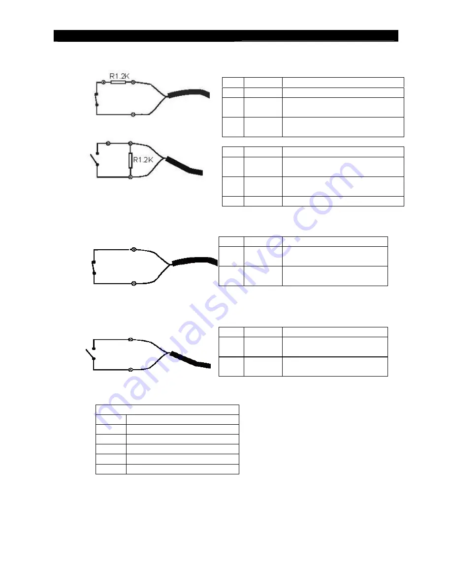
RX with Tamper Circuit and External Resistors
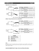
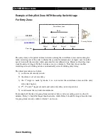
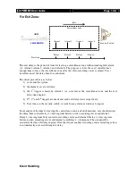
Single End of Line Configuration
Normal Close (NC)
Normal Open (NO)
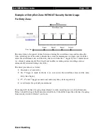
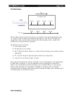
Without Tamper Detection Circuit Configuration
Normal Close (NC)
Normal Open (NO)
LEGEND
NO
Normally Open Alarm
NC
Normally Closed Alarm
O/C
Open Circuit
S/C
Short Circuit
LoZ
Low Impedance
HiZ
High Impedance
Notes:
The table below shows the summary between the resistance network and the condition result.
Note that this table is used as a reference. There may be a 10% tolerance for the resistance
value in the below table.
Term Status
Description
S/C TAMPER Wire short (point A and B)
LoZ NORMAL Sensor drive output close (point
B and C)
O/C ALARM Sensor drive output open (point
B and C)
Term Status
Description
S/C ALARM Sensor drive output close (point
A and B)
LoZ NORMAL Sensor drive output open (point
A and B)
O/C TAMPER Wire open (point A and B)
Term Status
Description
S/C NORMAL Sensor drive output close
(point A and B)
O/C ALARM Sensor drive output open
(point A and B)
Term Status
Description
S/C ALARM Sensor drive output close
(point A and B)
O/C NORMAL
Sensor drive output open
(point A and B)
sensor
drive
output
A
B
wire
sensor
drive
output
B
A
wire
C
sensor
drive
output
wire
A
B
sensor
drive
output
wire
B
A


