User
Guide
Page 7
Introduction
1.
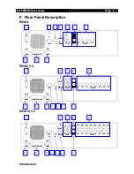
Video Output Connectors
A composite video signal with 1V p-p is output from this connector
PAL/CCIR format with 625 lines, 25 frames per second
NTSC/EIA format with 525 lines, 30 frames per second
2.
Video Input Connector
{Standard BNC connectors} for video source input
A composite video source from camera should be supplied to these connectors
CH1 – CH4 (RX364)
CH1 – CH8 (RX368_V2)
CH1 – CH16 (RX3616_V2)
3.
Audio In/Out Port
{Audio In} : Connect audio input device (e.g. microphone) with RCA jack to
RX
video recording server for recording. (Only 1 {Audio In} for RX364)
{Audio Out}: Connect audio output device (e.g. speaker) with RCA jack to
RX
video recording server and generate output audio signal
{Audio PA} : Connect audio output device (e.g. speaker) to
RX
video
recording server and generate audio signal to facilitate remote public addressing
4.
Ethernet Socket (10/100 Base-T)
This socket is used for connecting
RX
to the corporate computer network
(e.g. LAN)
This socket includes
{COL LED}
and
{LINK LED}
{COL LED}
: When ON, indicates that collision is occurring on the network
{LINK LED}
: When ON, indicates that
RX
is connecting to the network
and ready to function
5.
USB
For support firmware upgrade, setting import/export, USB modem and footage backup.
6.
RS 232 (Modem) Port
A {DB-9 Male Connector} of DTE format, capable for connecting to DCE such as
modem, ISDN terminal adapter
Pin number
Definition
Direction
1
CD
Input
2
RXD
Input
3
TXD
Output
4
DTR
Output
5
GND
–––
6
DSR
Input
7
RTS
Output
8
CTS
Input
9
–––


