A-11
Model 199 Differential Pressure Unit (DPU)
Section 3
Piping Diagrams
Diagrams for typical and special flow applications are presented on the fol
-
lowing pages. Use the diagram best suited for the application as a guide for
piping configuration.
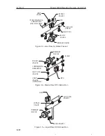
BLOCK VALVES
PRIMARY DEVICE
STATIC PRESSURE
CONNECTION
(USE ONLY ONE)
BYPASS
VALVES
VENT VALVE
SHUT-OFF
VALVES
DPU
Figure 3.1—Gas Flow, DPU Above Run
BLOCK
VALVES
PRIMARY
DEVICE
STATIC PRESSURE
CONNECTION
(USE ONLY ONE)
BYPASS
VALVES
VENT
VALVE
SHUT-OFF
VALVES
DPU
DRIP POTS
Figure 3.2—Gas Flow, DPU Below Run

