5
Model 289A Differential Pressure Indicating Switch
Section 1
Standard models can have one or two alarm switches. Each switch can be
connected to operate normally-opened or normally-closed. The direct-set
switch contacts are adjustable over a scale range of 5-95% nominal for SPDT
switches and 6-94% for DPDT switches.
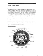
The cam rotates counterclockwise with increased pressure. In Figure 1.2, the
low switch is set at 25% differential pressure, and the high switch is set at
75% differential pressure.
Switches are available in several variations.
• SPDT: This is the standard model (low, high, or both)
• DPDT: Two switches are stacked and actuated by a single lever (low,
high, or both)
• Three or four SPDT: Switches have independent switch points.
Switches 1 and 3 are usually low switches set for decreasing pressures;
switches 2 and 4 are usually high switches set for increasing pressures.
Relays
Relays are actuated by internal switches and are available in several varia-
tions:
• one or two SPDT switches
• one or two DPDT switches
Wiring
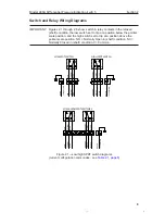
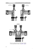
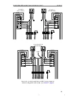
No. 22 AWG is used for internal wiring and No. 18 AWG is used for external
wiring.
Differential Pressure Unit (DPU)
For detailed information on the DPU, see the Model 199 DPU user manual in
Appendix A.
Specifications
General:
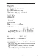
Actuating Unit (DPU) ...................... Model 199 DPU
Dial Size ......................................... 6 inches (150 mm)
Temperature Limits (Ambient) ........ -40°F (-40°C) to +180°F (+82°C)
Switch Repeatability ....................... ±0.25% of full scale
Switch Deadband ........................... ±5% (SPDT); ±6% (DPDT)
Switch Type .................................... Mechanical, Snap-Acting; all switches are SPDT
(DPDT switches are stacked SPDT switches with a
common actuator)
Relay Contact Type ........................ Single Pole, Double Throw (SPDT)
Double Pole, Double Throw (DPDT)
Adjustability .................................... 5% to 95% of factory calibrated scale
Activation ........................................ Increasing or decreasing scale


