E N G I N E E R E D & P R O C E S S V A L V E S
07/2011 / IOM-GEN-TWIN-03
21
Installation, Operation and Maintenance Manual
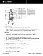
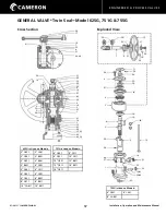
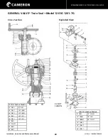
OPERATOR DISASSEMBLY
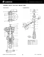
1.
Unscrew (37) and remove indicator flag (9).
2.
Remove indicator shaft protector (22).
3.
Unbolt and remove gear housing cover (7).
4.
Remove upper stem nut (15).
5.
Remove upper bearing (25).
6.
Remove capscrew (34), handwheel washer (16), hand
wheel (11) and woodruff key (17).
7.
Unbolt and remove bearing cap (8).
CAUTION: DO NOT
DAMAGE PLASTIC SHIMS.
8.
Screw out worm shaft (6). Front bearing cone (27) and
cup (28) and rear bearing cone (27) will come out with
the worm shaft. Rear bearing cup (28) can then be
removed from gear housing.
9.
Remove the worm gear (5) and key (18).
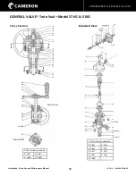
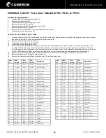
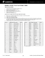
GENERAL VALVE
®
Twin Seal
™
Model 1261G & 1261-7G
Item No. 1261G Part
No.
1261-7G
Part No.
Description
Req’d
1
21-621
21-621
Operator Housing
1
2
21-518
21-518
Gear Housing
1
3
22-552
22-552
Upper Stem
1
4
22-553
22-553
Lower Stem
1
5
23-472
23-472
Worm Gear
1
6
24-428
24-428
Worm Shaft
1
7
26-513
26-513
Gear Housing Cover
1
8
26-514
26-514
Bearing Cap
1
9
27-406
27-406
Indicator Flag
1
10
27-488
27-488
Indicator Shaft
1
11
28-402
28-402
Handwheel
1
12
41-402
41-402
Drive Pin*
1
13
41-496
41-496
Guide Pin
1
14
41-411
41-411
Coupling Pin
1
15
42-403
42-403
Nut
1
16
44-401
44-401
Handwheel Washer
1
17
45-402
45-402
Woodruff Key
1
18
45-404
45-404
Key
1
19
48-412
48-412
Roller
1
20
62-13
62-13
O-Ring
1
21
62-208
62-208
O-Ring
1
22
64-411
64-411
Protector
1
23
64-416
64-416
Plastic Plug
2
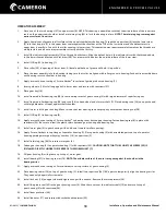
10. Unbolt and remove the gear housing (2).
11. Remove the retaining ring (40).
12. Unbolt and remove the guide pin (13).
13. Pull the upper stem (3) with the lower stem (4), roller
(19), two bearings (26) and indicator shaft (10) out
through the top of the housing (1). If the bearings are
snug in the housing, install the worm gear (5) with its
key (18) on the upper stem upside down (hub up).
Turn the gear counter-clockwise to raise the lower stem
as far as possible. Insert a 1 1/2” diameter bar through the
two holes in the bottom of the housing. Using a pipe
wrench on the gear hub, turn clockwise and jack the
bearing clear of the housing.
14. Remove the socket head capscrew (38) and push the
indicator shaft subassembly (10) out through the bottom
on the lower stem (4).
15. Remove the lower stem (4) from the upper stem (3).
16. Remove the bearings (26) from the upper stem (3).
Item No. 1261G Part
No.
1261-7G
Part No.
Description
Req’d
24
65-401
65-401
Grease Seal
1
25
66-404
66-404
Ball Bearing
2
26
66-411
66-411
Ball Bearing
2
27
66-465
66-465
Bearing Cone
2
28
66-466
66-466
Bearing Cup
1
29
69-414
69-414
Spinner Handle
4
30
72-2
72-2
Capscrew
1
31
72-3
72-3
Capscrew
2
32
72-4
72-4
Capscrew
8
33
72-7
72-7
Capscrew
1
34
72-8
72-8
Capscrew
7
35
72-13
72-13
Capscrew
2
36
72-21
72-21
Capscrew
1
37
73-28
74-6
Screw
1
38
73-28
74-12
Set Screw
2
39
76-412
76-412
Lube Fitting
1
40
78-405
78-405
Retaining Ring
2
41
78-407
78-407
Retaining Ring
1
42
93-413
93-413
Cover
1
43
-
26-712
Adapter
1


