E N G I N E E R E D & P R O C E S S V A L V E S
07/2011 / IOM-GEN-TWIN-03
27
Installation, Operation and Maintenance Manual
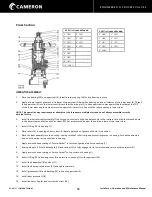
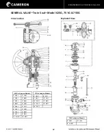
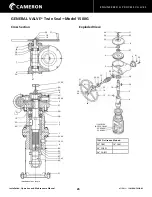
OPERATOR DISASSEMBLY
1.
Turn worm shaft counter-clockwise to full open position.
2.
Remove set screw (39) and indicator flag (11)
3.
Remove the stem protector (24).
4.
Unbolt and remove the gear housing cover (8).
5.
Remove the set screw (39), and upper stem nut (17).
6.
Remove the ball bearing (27).
7.
Unbolt and remove bearing cap (10).
CAUTION: DO NOT DAMAGE THE PLASTIC SHIMS UNDER MOTOR ADAPTER.
8.
Remove the worm shaft (7) and taper bearings consisting of cones (29) and cups (30).
9.
Remove worm gear (6) and key (20).
10. Unbolt and remove the gear housing (3).
11. Unbolt and remove the guide pin (16).
12. Pull the upper stem (5) and lower stem (4) with bearings (28), bearing retainer and roller (21) out through the top of the upper
housing (2). If bearings are snug in the upper housing, remove the upper and lower stems with the roller through the bottom of
the lower housing. Unbolt the upper and lower housings and remove the bearings with a suitable puller.
13. Separate the upper and lower stems and remove the nut (43) and indicator shaft (12).
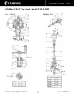
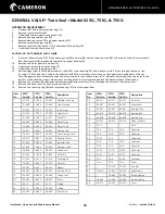
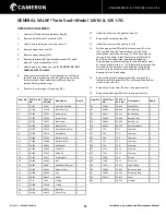
GENERAL VALVE
®
Twin Seal
™
Model 1500G
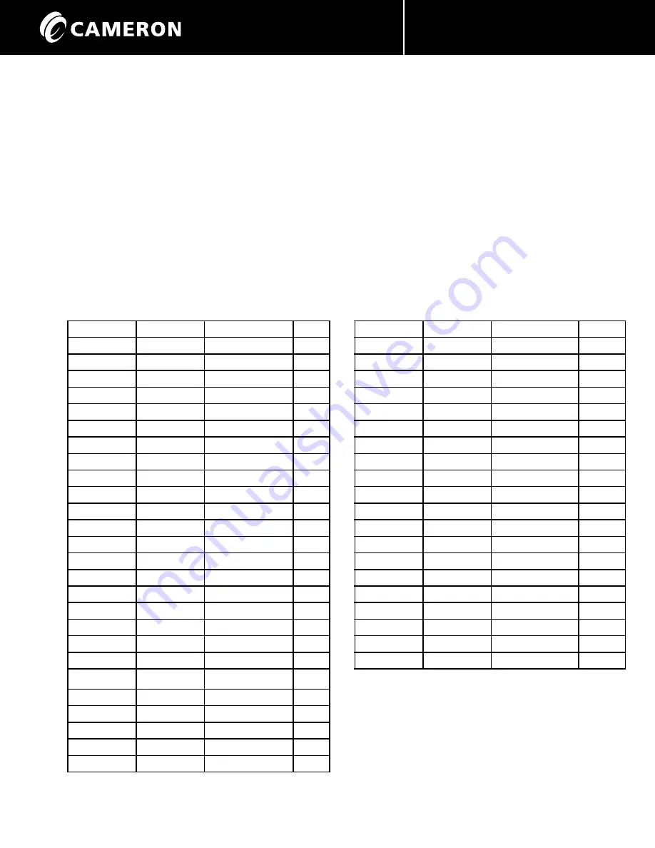
Item No.
1500G Part No. Description
Req’d
27
66-424
Ball Bearing
1
28
66-425
Ball Bearing
1
29
66-454
Bearing Cone
2
30
66-463
Bearing Cup
2
31
69-414
Spinner Handle
1
32
71-109
Stud
12
33
72-5
Capscrew
2
34
72-8
Capscrew
1
35
72-26
Capscrew
8
36
72-64
Capscrew
12
37
73-87
Capscrew
12
38
73-124
Capscrew
12
39
74-6
Screw
1
40
75-408
Nut
24
41
76-412
Lube Fitting
2
42
76-470
Pipe Plug
1
43
75-441
Nut
1
44
72-21
Capscrew
30
45
75-442
Coupling Pin Nut
2
46
32-452
Spacer
1
Item No.
1500G Part No. Description
Req’d
1
21-572
Lower Housing
1
2
21-571
Upper Housing
1
3
21-573
Gear Housing
1
4
22-510
Lower Stem
1
5
22-509
Upper Stem
1
6
23-411
Worm Gear
1
7
24-425
Worm Shaft
1
8
26-515
Gear Housing Cover 1
9
26-488
Bearing Cap
1
10
26-489
Bearing Cap
1
11
27-406
Indicator Flag
1
12
27-450
Indicator Shaft
1
13
28-432
Handwheel
1
14
41-474
Drive Pin*
1
15
32-410
Coupling Pin
1
16
41-474
Guide Pin
1
17
75-441
Nut
1
18
44-401
Washer
1
19
45-402
Key
1
20
45-414
Key
1
21
48-408
Roller
1
22
62-20
O-Ring
1
23
62-89
O-Ring
1
24
64-412
Protector
1
25
-
Oper. Shield
2
26
65-401
Grease Seal
1
*not available separately

