24
TC-003001-30 / Rev 01
Feb-02
i.
Install the torque pins and the locating pin into the correctly sized holes.
j.
Install the gear adapter plate over the stem. The plate should fit over all the pins including the
locating pin, with the key grooves oriented towards the valve body markings and the tailpiece.
k.
Install all the cap screws and torque as required per Table 7.
l.
Install the key. The key should not stick above the stem.
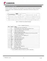
Figure 15 – Gear Adapter Plate Assembly
19.
Install the stem retaining screw(s). Thread the screws until contacting the stem and turn back a half turn.
CAUTION: If the stem retaining screw is not backed off and remains in contact with the stem, the valve torque
may increase and affect actuator performance.
20.
If removed, tape all check valves and external fittings with Teflon tape and install them at this time. Use
the installation torques noted in Table 8.
21.
The body stud nuts and cap screws should be torqued as required per Table 7, in a cross pattern
sequence. Check each at least twice to make sure they have been tightened correctly.
22.
If the valve requires a gear operator, see Gear Operator Assembly. If otherwise actuated, carefully read
the actuator operation manual before installation.


