33
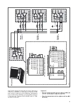
Slave
1
Master
S
IN
E
A
X
D
M
E
4
40
26
25
24
23
Tx+/Rx+
GND
Tx-/Rx-
S
IN
E
A
X
D
M
E
4
40
26
25
24
23
Tx+/Rx+
GND
Tx-/Rx-
EURAX DME 440
2z
2d
6z
6d
Tx+/Rx+
GND
Tx-/Rx-
Tx+/Rx+
GND
Tx-/Rx-
Slave
2
S
IN
E
A
X
D
M
E
4
40
26
25
24
23
Tx+/Rx+
GND
Tx-/Rx-
GND
Slave
n
+ 5
V
Built-in RS485 interface car
d
Signal GND
Data Out
A
Data Out
B
Data In
A
Data In
B
Handshake Out
A
Handshake Out
B
Handshake In
A
Handshake In
B
PC with interface 13601 of W &
T
5
1
6
2
7
3
8
4
9
With converter RS232/RS485
GND Signal GND
D
in
D
at
a
O
ut
A
D
o
ut
D
at
a
O
ut
B
Data In
A
Data in
B
Handshake Out
A
Handshake Out
B
Handshake In
A
Handshake In
B
PC
5
1
6
2
7
3
8
4
9
GND
TxD
RxD
DTR
DSR
R
T
S
CTS
5
3
2
4
6
7
8
Interface 86201 of W &
T
Fig. 8
Fig. 8 shows the connection of transducers DME 440 to
the MODBUS. The RS 485 interface can be realized by
means of PC built-in interface cards or interface converters.
Both is shown using i.e. the interfaces 13601 and 86201 of
W & T (Wiesemann & Theis GmbH). They are configured for
a 2-wire application with automatic control of data direction.
These interfaces provide a galvanical isolation and a built-in
termination network.
Important:
– Each device connected to the bus must have a unique
address (1 to 247, default ex factory: 247).
– All devices must be adjusted to the same baudrate.
Summary of Contents for SINEAX DME 440
Page 2: ...2 ...

