13
English
1
“Input” and “output” in this case refer to the direction of power
supply fl ow.
4. Technical data
Input signal E
1
(Input circuit between signal isolator and power pack)
DC current signal I
E
: 4...20
mA
Voltage U
E
:
12…30 V DC
Overload capacity:
≤ 50 mA continuous
Output signal A
1
(Input circuit between signal isolator and 2-wire transmit-
ter)
DC current signal I
A
: 4...20
mA
Voltage U
A
(for I
E
= 20 mA and U
E
= 22 V):
> 19.3 V
with standard (non-Ex) version,
not designed for communications protocol
> 18.5 V
with standard (non-Ex) version,
designed for FSK communication
> 14.3 V
with Ex versions,
not designed for communications protocol
> 13.3 V
with Ex versions,
designed for FSK communication
Voltage drop U
V
= U
E
– U
A
(at U
E
) 12…22 V:
< 2.7 V
with standard (non-Ex) version,
not designed for communications protocol
< 3.5 V
with standard (non-Ex) version,
designed for FSK communication
< 7.7 V
with Ex versions,
not designed for communications protocol
< 8.7 V
with Ex versions,
designed for FSK communication
Residual ripple:
< 20 mV ss (120 kHz)
Time constant:
Approx. 5 ms
Accuracy data
Error: < ± 0.2%
(Reference value 20 mA of output
signal, including typical linearity
error < ± 0.1%)
Ambient conditions
Commissioning
temperature:
– 10 to + 40 °C
Operating temperature: – 25 to + 40 °C,
Ex –20
to + 40 °C
Storage temperature:
– 40 to +70 °C
Annual mean
relative humidity:
75%
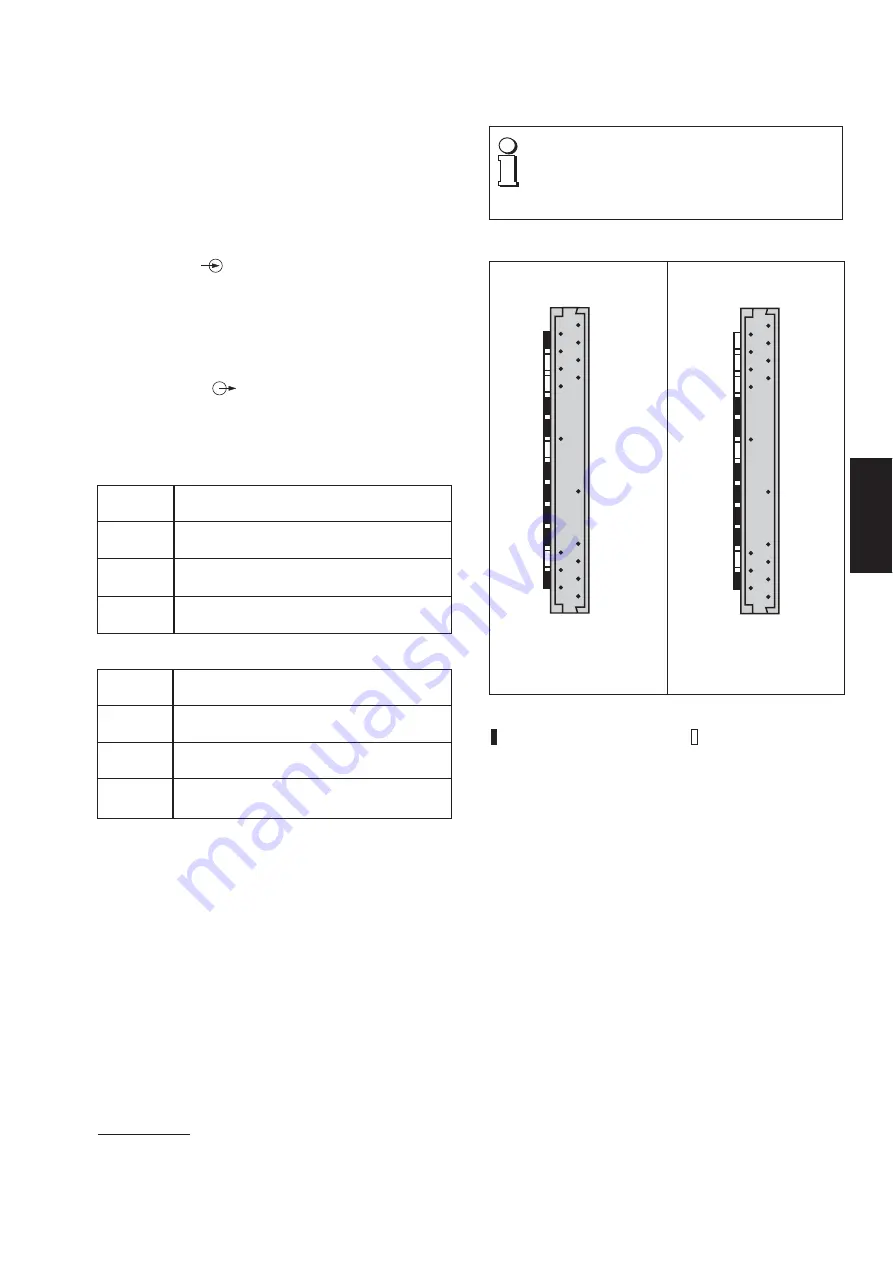
5. Mechanical coding of the plug-in module
Where there is a danger of inserting a module in the
wrong slot, the possibility has to be excluded as
prescribed in EN 50 020, Section 6.3.2.
To this end,
the units must be supplied already equipped with
coding inserts as shown in Figures 3 and 4.
Fig. 4. Coding of the plug-in
module type SI 815-62.. in
Ex-version, (output signal
intrinsically safe).
Fig. 3. Coding of the plug-in
module type SI 815-61.. in
standard (non-Ex) version.
Legend to Figs. 3 and 4:
= With set of code
= Without set of code
Back
A
B
C
D
E
F
G
H
I
K
L
M
Back
A
B
C
D
E
F
G
H
I
K
L
M
The series also includes “intrinsically safe” versions
[EEx ia] IIC with an intrinsically safe measurement/supply
circuit. These operate in conjunction with intrinsically safe
two-wire transmitters located in explosion hazard areas.
Summary of Contents for SIRAX SI 815-6
Page 2: ...2 ...


