background image

7

HVLP Paint Sprayers

Operating Instructions and Parts Manual

www.chpower.com

HV2100, HV2105

Operation 

(Cont.)

13. Pull the trigger. Notice the pattern

has become smaller. (You can
continue reducing the material
flow and move the spray gun even
closer to the surface and the
pattern will keep getting smaller).

14. Rotate the air cap to a diagonal

position (See Figure 2).

15. Every so often, turn the material

flow knob to a different position.
Also, change the distance of the
spray gun from work surface. Notice
how doing this changes pattern size.

There is one additional control to
know. If you loosen the air cap locking
ring, approximately 1-2 turns, you can
control the fan pattern size and trim or
feather the edge of the fan pattern
itself. This should be considered a
secondary control, the primary fan
pattern size being adjusted between
fluid flow and distance of the spray
gun from the work piece.

Even when the turbine is turned off,
pressure will remain in the spray cup.
When trigger is pulled back, a stream
of fluid will flow. To prevent accidents,
turn material flow knob clockwise until
it is completely closed, locking trigger
in closed position.

NOTE:

It is not necessary to empty and

clean your spray gun when you pause
between applications. Be sure,
however, to clean your spray gun
thoroughly at the end of your work
session.

Clean spray gun 
thoroughly at end

of work session. Do not allow coating
to dry in spray gun overnight or at any
time when not in use.

Extra caution should be taken when
spraying coatings that have a catalyst
or hardener added since many of these
coatings have short pot life. These

NOTICE

!

WARNING

coatings can harden in your spray gun
quickly, making cleaning difficult or
impossible. Read manufacturer’s
coating instructions to help determine
how quickly a particular coating will
harden in your spray gun.

SPRAYING TECHNIQUE

Practice is the key element in achieving
a proper spray technique. Never try to
rush the spray finishing process. Learn
the properties of the coating you will
be spraying. Build up layers of material
(3-4 applications, or more if needed).
Sand between coats, if needed, and
allow proper drying time between
applications.

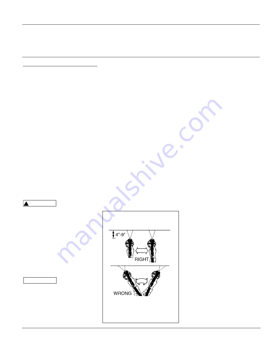
Remember to keep the distance of the
spray gun the same when moving
across your work (called a “pass”). Do
not rotate or turn your wrist from side
to side (See Figure 3). Move the spray
gun across your work from end to end.
Be sure to maintain the same speed of
movement. This will ensure an even
application of coating. Always release
the trigger at the end of a pass.

Continue spraying in the opposite
direction overlapping your previous
coat by 1/3 to 1/2. When finished, you
should have an even wet coat on your
work. If you have dry spots, you have
overlapped too widely.

If you have heavy or wet spots, you
have overlapped too much. When
spraying a large or pre-assembled
piece, start at the top and work down.
Try to spray the hard-to-reach surfaces
first. Keep in mind that a light, wet
film will generally produce better
results than a heavy, wet coat. When
spraying a vertical surface, apply a
thin“tack” coat first, followed by a
normal light wet coat. This technique
will help prevent “runs” and “sags.”

When using your Spray Gun you
control five variables. 

1. Fluid flow

2. Distance of the spray gun from

your work. (4"–8" is average. Closer
if necessary.)

3. Pattern Direction (vertical fan,

horizontal fan and round)

4. Speed of application

5. Fan pattern control (adjust air cap

ring)

NOTE:

Items 1, 2, and 4 directly relate

to each other.

RUNNING MULTIPLE SPRAY GUNS
WITH A TURBINE

It is possible to run the 4-stage turbine
system with two spray guns at the
same time by installing “Y” Connector
to the turbine outlet port.

IMPORTANT: 

If the “Y” connector is

installed and only one spray gun
operated, the 2nd outlet must be
capped or closed so that performance
to the single spray gun will not be
affected.

Figure 3 - Proper Spray Technique

Summary of Contents for HV2100

Page 1: ...Parts Manual IN422300AV 11 02 BUILT TO LAST Thank you for purchasing a Campbell Hausfeld product If you have any technical questions about this product please call 1 800 626 4401 For Parts and Access...

Page 2: ...ATED HYDROCARBONS WITH THIS EQUIPMENT Consult the paint or solvent product label or Material Safety Data Sheets MSDS to help determine if it contains halogenated hydrocarbons Make sure the room is wel...

Page 3: ...modify the plug provided If the plug does not fit the outlet have the proper outlet installed by a qualified electrician 3 This product is for use on a nominal 120 volt circuit and has a grounding plu...

Page 4: ...e ring Your air hose will be locked into place To disconnect pull back on the connector to release the air hose If you have just finished spraying the metal coupler at the turbine end may be hot 2 Plu...

Page 5: ...to spray Atomizing pressure and fluid viscosity directly relate to the efficiency of the equipment operation and the quality of the results that you will achieve The available air volume and pressure...

Page 6: ...counterclockwise and moving the spray gun closer or further away from your work piece A little practice will enable you to master this technique PRACTICE Practice using your spray gun by following the...

Page 7: ...AYING TECHNIQUE Practice is the key element in achieving a proper spray technique Never try to rush the spray finishing process Learn the properties of the coating you will be spraying Build up layers...

Page 8: ...dle Reverse these two fittings to use the air hose coupled to the handle OPTION 2 This will allow you to control the air flow and create textured or splatter paint effects To install remove blanking p...

Page 9: ...e 6 for viscosity guidelines 2 Carefully loosen the four wing nuts to remove the pot lid Open the pressure pot NOTE You may have to disconnect the air hose from the compressor when opening the lid Be...

Page 10: ...ockwise 3 You will hear a hissing sound The pressure in the pot is now releasing You will also notice that pressure gauge will lower to 0 psi Once there is no more pressure in the pot it is safe to op...

Page 11: ...ashers and gaskets are replaced correctly e Oil the needle spring and put a spot of oil on the gland seal to prevent the needle from sticking To adjust the gland nut tighten until needle sticks and th...

Page 12: ...material coming out 3 Too much air power behind pressure stream 4 Tip needle assembly too large Coating not strained thinned properly N A This is normal and expected Bleeder type guns are set up this...

Page 13: ...25 25 Air Hose Part No HV0126 For Replacement Parts Call 1 800 626 4401 Please provide following information Model number Serial number if any Part descriptions and number as shown in parts list Addre...

Page 14: ...14 www chpower com Operating Instructions and Parts Manual HV2100 HV2105 Spray Gun with Quick Release Cup...

Page 15: ...00mm Needle stainless 1 50mm Needle stainless 2 00mm Needle stainless 2 50mm 16 Needle spring stainless HV104513AV 1 17 Adjuster insert HV104503AV 1 18 Material flow knob HV104502AV 1 19 Gun casting h...

Page 16: ...www chpower com Operating Instructions and Parts Manual HV2100 HV2105 16 Cart Assembly For Model HV2105 only...

Page 17: ...1 8 male NPT x 1 4 male hose barb 90o A 4503 1 15 Air hose clip stainless steel A 4033 2 16 1 4 Air hose per foot A 2116 3 17 1 4 x 1 4 Female swivel barb A 2119 1 18 Quick connect female with 1 4 ma...

Page 18: ...18 Operating Instructions and Parts Manual www chpower com HV2100 HV2105 Fluid Tank Assembly For Model HV2105 only...

Page 19: ...911 4 12 Wing nut A 4912 4 13 Pressure regulator A 4913 1 14 Pressure gauge A 4914 1 15 On off valve A 4915 1 16 3 Way block A 4916 1 17 1 4 x 1 4 Adapter A 4917 3 18 3 Way block A 4918 1 19 Adapter A...

Page 20: ...HAUSFELD PRODUCT Some states do not allow the exclusion or limitation of incidental or consequential damages so the above limitation or exclusion may not apply to you C Any failure that results from a...

Reviews: