background image

020C Wind Direction Sensor 

11 

EPA, 1987:  

On-Site Meteorological Program Guidance for Regulatory 

Modeling Applications,

 EPA-450/4-87-013, Office of Air Quality Planning 

and Standards, Research Triangle Park, NC  27711. 

The State Climatologist, 1985:  

Publication of the American Association of 

State Climatologists:  Height and Exposure Standards

, for Sensors on 

Automated Weather Stations, vol. 9, No. 4. 

WMO, 1983:  

Guide to Meteorological Instruments and Methods of 

Observation,

 World Meteorological Organization, No. 8, 5th edition, 

Geneva, Switzerland. 


Summary of Contents for 020C

Page 1: ...INSTRUCTION MANUAL 020C Wind Direction Sensor Revision 6 16 C o p y r i g h t 2 0 1 2 2 0 1 6 C a m p b e l l S c i e n t i f i c I n c ...

Page 2: ......

Page 3: ...ducts to CSI CSI will return such Products by surface carrier prepaid within the continental United States of America To all other locations CSI will return such Products best way CIP port of entry per Incoterms 2010 This warranty shall not apply to any Products which have been subjected to modification misuse neglect improper service accidents of nature or shipping damage This warranty is in lieu...

Page 4: ... address is CAMPBELL SCIENTIFIC INC RMA _____ 815 West 1800 North Logan Utah 84321 1784 For all returns the customer must fill out a Statement of Product Cleanliness and Decontamination form and comply with the requirements specified in it The form is available from our website at www campbellsci com repair A completed form must be either emailed to repair campbellsci com or faxed to 435 227 9106 ...

Page 5: ...e beginning work Wear a hardhat and eye protection and take other appropriate safety precautions while working on or around tripods and towers Do not climb tripods or towers at any time and prohibit climbing by other persons Take reasonable precautions to secure tripod and tower sites from trespassers Use only manufacturer recommended parts materials and tools Utility and Electrical You can be kil...

Page 6: ......

Page 7: ...on 6 7 2 1 1 Output Voltage 6 7 3 Siting 7 7 4 Assembly and Mounting 7 7 5 Sensor Check Out 9 8 Troubleshooting and Maintenance 9 8 1 Troubleshooting 10 8 2 Maintenance Schedule 10 9 References 10 Appendices A Importing Short Cut Code Into CRBasic Editor A 1 B Example Program B 1 C Wind Direction Sensor Orientation C 1 C 1 Determining True North and Sensor Orientation C 1 Figures 7 1 CM220 right a...

Page 8: ...ubtracted from 360 to get true North C 3 C 3 Declination angles west of true North are added to 0 to get true North C 3 Tables 7 1 Wire Color Wire Function and Connections 5 8 1 020C Wind Direction Sensor Troubleshooting 10 CRBasic Example B 1 CR1000 Example Program B 1 ...

Page 9: ...lease handle it with care If the 020C will be installed at heights over six feet be familiar with tower safety and follow safe tower climbing procedures Danger Use extreme care when working near overhead electrical wires Check for overhead wires before mounting the 020C or before raising a tower 3 Initial Inspection Upon receipt of the 020C inspect packaging and contents for damage File damage cla...

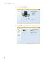
Page 10: ... Wind Direction Sensor 2 Use the following procedure to get started 1 Open Short Cut Click New Program 2 Select Datalogger Model and Scan Interval default of 5 seconds is OK for most applications Click Next ...

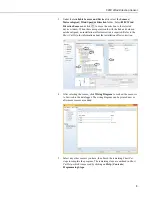
Page 11: ...lation offset correction is required Refer to the Short Cut Help for information about the installation offset correction 4 After selecting the sensor click Wiring Diagram to see how the sensor is to be wired to the datalogger The wiring diagram can be printed now or after more sensors are added 5 Select any other sensors you have then finish the remaining Short Cut steps to complete the program T...

Page 12: ... aspiration through the bearings thereby greatly increasing bearing life It also includes electrical field surge protection that reduces problems associated with static fields near miss lightning hits and poor grounding systems The vane assembly is easily installed or replaced without requiring recalibration All sensor components are constructed with stainless steel and anodized aluminum 6 Specifi...

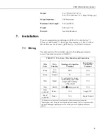
Page 13: ...ct to the datalogger and power source Connections are given in TABLE 7 1 TABLE 7 1 Wire Color Wire Function and Connections Wire Color Wire Function Datalogger Connection Terminal Power Source Connection Terminal White 12 V Power 12V N A Green Ground G N A Blue Signal U configured for single ended analog input1 SE single ended analog voltage input N A Clear Shield AG or analog ground N A Red2 opti...

Page 14: ...SE Instruction The VoltSE measurement instruction programs the datalogger to measure the 020C VoltSE Dest Reps Range SEChan MeasOff SettlingTime Integ fnotch Mult Offset Use 0 072 for the Mult and 0 0 for the Offset For Range use mV5000 CR1000 CR800 CR6 CR3000 CR5000 or mV2500 CR300 You need to move a jumper to use the mV2500 range Section 7 2 1 1 Output Voltage p 6 If the sensor will be in electr...

Page 15: ...unting Bushing compass and declination angle for the site small screwdriver provided with datalogger UV resistant cable ties small pair of diagonal cutting pliers 6 to 10 inch torpedo or spirit level CM220 Right Angle Mounting Kit or 3 4 x 1 inch Nu Rail Crossover Fitting pn 1049 1 Mount the CM200 series crossarm to the tripod or tower Orient the crossarm north to south with the Nu Rail fitting or...

Page 16: ... bushing such that the counterweight alignment notches FIGURE 7 3 and alignment screw FIGURE 7 1 FIGURE 7 2 point true south Sensor column CM220 mounting bracket CM200 series crossarm U bolt Alignment set screw U bolt Bushing Cable connector Bushing Set screw 1 x 3 4 Nu Rail fitting Set screw Alignment screw CM200 series crossarm ...

Page 17: ...ck Out With the datalogger measuring the sensor 020C output moves up scale as the vane rotates clockwise as seen from above the sensor Output will progress up scale until the 360 full scale mark has been reached Output then drops to near 0 When the notches on the rotating hub and the column of the sensor are exactly aligned the output will be 180 8 Troubleshooting and Maintenance All factory repai...

Page 18: ...place potentiometer Contact Campbell Scientific for repair authorization No change in wind direction output below 2 to 5 mph Bad bearings Replace bearings Contact Campbell Scientific for repair authorization 8 2 Maintenance Schedule 6 to 12 Month Intervals 1 Inspect sensor for proper operation per Section 7 5 Sensor Check Out p 9 2 Return to Campbell Scientific for calibration 12 to 24 Month Inter...

Page 19: ... and Standards Research Triangle Park NC 27711 The State Climatologist 1985 Publication of the American Association of State Climatologists Height and Exposure Standards for Sensors on Automated Weather Stations vol 9 No 4 WMO 1983 Guide to Meteorological Instruments and Methods of Observation World Meteorological Organization No 8 5th edition Geneva Switzerland ...

Page 20: ...020C Wind Direction Sensor 12 ...

Page 21: ...ut Make note of the file name used when saving the Short Cut program 2 Open CRBasic Editor 3 Click File Open Assuming the default paths were used when Short Cut was installed navigate to C CampbellSci SCWin folder The file of interest has the CR300 CR6 CR8 CR1 CR3 or CR5 extension Select the file and click Open 4 Immediately save the file in a folder different from C Campbellsci SCWin or save the ...

Page 22: ......

Page 23: ...10 Min 10 Sample 1 WindDir FP2 EndTable DataTable Table2 True 1 DataInterval 0 1440 Min 10 Minimum 1 BattV FP2 False False EndTable Main Program BeginProg Main Scan Scan 1 Sec 1 0 Default Datalogger Battery Voltage measurement BattV Battery BattV Default Wiring Panel Temperature measurement PTemp_C PanelTemp PTemp_C _60Hz 020C Wind Direction Sensor measurement WindDir VoltSe WindDir 1 mV5000 1 1 0...

Page 24: ......

Page 25: ...d negative and are subtracted from 360 degrees to get true North as shown in FIGURE C 2 0 and 360 are the same point on a compass For example the declination for Logan Utah is 13 5 East so true North is 360 13 5 or 346 5 as read on a compass Declination angles west of true North are considered positive and are added to 0 degrees to get true North as shown in FIGURE C 3 Orientation is most easily d...

Page 26: ...Appendix C Wind Direction Sensor Orientation C 2 FIGURE C 1 Magnetic declination for the contiguous United States 2004 ...

Page 27: ... Wind Direction Sensor Orientation C 3 FIGURE C 2 Declination angles east of true North are subtracted from 360 to get true North FIGURE C 3 Declination angles west of true North are added to 0 to get true North ...

Page 28: ...Appendix C Wind Direction Sensor Orientation C 4 ...

Page 29: ......

Page 30: ...Rua Apinagés nbr 2018 Perdizes CEP 01258 00 São Paulo SP BRASIL www campbellsci com br vendas campbellsci com br Campbell Scientific Canada Corp 14532 131 Avenue NW Edmonton AB T5L 4X4 CANADA www campbellsci ca dataloggers campbellsci ca Campbell Scientific Centro Caribe S A 300 N Cementerio Edificio Breller Santo Domingo Heredia 40305 COSTA RICA www campbellsci cc info campbellsci cc Campbell Sci...

Reviews: