background image

AM16/32 Relay Analog Multiplexer

24

6.3  Half Bridge Measurements

Measurements of this type may be subdivided into three categories
based on completion resistance and the presence or absence of
measured excitation.  If the sensor's completion resistor(s) are installed
at the datalogger panel (example: a CSI 107 probe modified for
multiplexer use), then three probes per SET may be excited and
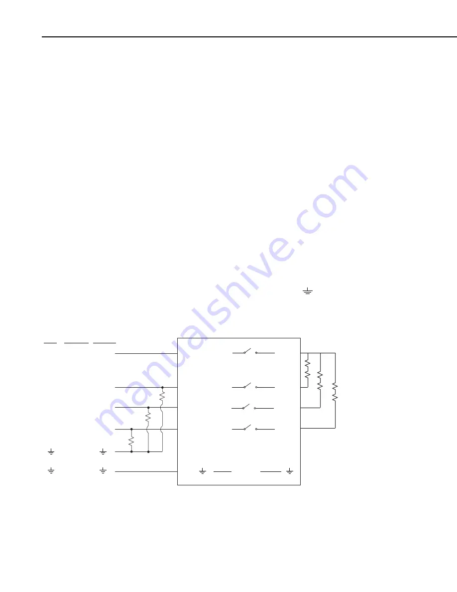
measured in “4X16” mode (Figure 12).  However, if the circuit is
completed within the sensor (e.g. potentiometers), then excitation,
wiper signal, and ground must be multiplexed.  Because excitation and
ground may be multiplexed in common, up to two sensors per SET
may be measured (Figure 13).  If measured excitation is required (i.e.
four wire half-bridge), then only one sensor per SET of four may be
measured (Figure 14).

6.3.1  Half Bridge Measurement with Completion Resistor at

Datalogger

Sensor to Multiplexer wiring - up to three half bridges may be
connected to one input SET in “4X16” mode, provided that the
sensors’ three completion resistors are located at the datalogger
(Figure 12).

Multiplexer to Datalogger wiring -  Signal lines from the multiplexer
COM terminals tie to three consecutive single-ended analog input
channels.  Three precision completion resistors connect from analog
input channels to analog ground in CR10(X) or to “

” in the

CR23X, 21X or CR7.

21x

CR7

CR10(X)

CR23X/

CR5000

"4 X 16" Mode

E

E

H

H

AG

G

E/VX

H

L

L

L

H

H

H

COM H (ODD)

COM L

COM H (EVEN)

COM L

ODD H

ODD L

EVEN H 

EVEN L

SHIELD

SENSOR SHIELDS

COM

MUXSIGNAL

SHIELD

FIGURE 12.  Half Bridge (Modified 107 Temperature Probe) Hook-up and Measurement.

CR23X/

21X

CR1000/

CR7

CR10(X) CR5000

Summary of Contents for AM16/32

Page 1: ...INSTRUCTION MANUAL AM16 32 Relay Multiplexer Revision 9 04 C o p y r i g h t c 1 9 8 7 2 0 0 4 C a m p b e l l S c i e n t i f i c I n c...

Page 2: ...ther warranties expressed or implied including warranties of merchantability or fitness for a particular purpose CAMPBELL SCIENTIFIC INC is not liable for special indirect incidental or consequential...

Page 3: ...Datalogger Programming 10 5 1 Single Loop Instruction Sequence 11 5 2 Multiple Loop Instruction Sequence 16 5 3 CR5000 and CR1000 Programming 18 5 3 1 CR5000 Programming 19 5 3 2 CR1000 Programming 2...

Page 4: ...Hookup 4x16 Mode 9 6 SCWIN Short Cut for Windows Program Builder 10 7 Example 4X16 Mode Program Loops for CR23X CR10 X 21X and CR7 Dataloggers 14 8 Example 2X32 Mode Program Loops for CR23X CR10 X 21X...

Page 5: ...easurement Customers who need to switch power are directed to Campbell Scientific s SDM CD16AC A6REL 12 or A21REL 12 relays Changing the setting of the mode switch from 4X16 to 2X32 connects COM ODD H...

Page 6: ...This is a blank page...

Page 7: ...depends primarily on the type s of sensors to be scanned The following guidelines assume identical sensors Up to 32 single ended or differential analog sensors that do not require excitation For exam...

Page 8: ...cm x 23 9 cm x 4 6 cm 4 0 x 9 4 x 1 8 anodized aluminum case Figure 1 The aluminum case is intended to reduce temperature gradients across the AM16 32 s terminal strips An aluminum cover plate is also...

Page 9: ...typical in 4 x 16 mode Reset A continuous signal between 3 5 VDC and 16 VDC holds the AM16 32 in an active state where a clock pulse can trigger a channel advance A signal voltage 0 9VDC deactivates t...

Page 10: ...oy Wiper to N O contact capacitance 0 5 pF Typical low current 30 mA life 5 x 10 7 operations Relay Switching Thermal emf 0 3 uV typical 0 5 uV maximum Characteristics applying 11 3 14 VDC Operate tim...

Page 11: ...sses the use of sensor measurement terminals 4 1 The Control Terminals The CR5000 CR1000 CR23X CR10 X 21X and CR7 dataloggers connect to the AM16 32 as shown in Figure 3 4x16 mode Figure 3 depicts con...

Page 12: ...the case of the 21X or CR7 with older PROMS Instruction 20 is commonly used The CR5000 and CR1000 uses the PortSet instruction to control the reset line 4 1 2 Clock Pulsing the AM16 32 CLK line high R...

Page 13: ...hould connect to a datalogger ground terminal or G via the MUXSIGNAL cable or equivalent also according to Figure 5 see 4 2 1 The datalogger itself must connect to earth ground by one of the methods d...

Page 14: ...strip when the 12V supply is used to power peripherals This limitation reduces the number of available analog input channels and may mandate the use of an external supply for the AM16 32 Figure 4 FIGU...

Page 15: ...6 groups panel switch set to 4X16 or into 32 groups panel switch set to 2X32 The groups consists of four or two Simultaneously Enabled Terminals SETs With panel switch set to 4X16 mode the blue channe...

Page 16: ...connects to COM EVEN H and COM ODD L connects to COM EVEN L when panel switch is in 2X32 mode 5 Datalogger Programming A good way for the beginner or veteran datalogger programmer to create an AM16 3...

Page 17: ...rogram exits the loop 3 Clock and Delay With the CR23X and CR10 X the clock line is connected to a control port Instruction 86 with the pulse port command 71 78 pulses the clock line high for 10 ms In...

Page 18: ...nstructions is indexed For example 2 sensors per SET one rep in each of two measurement instructions two measurement values assigned to indexed input locations one begins with input location 1 the oth...

Page 19: ...ons must be assigned using the datalogger A mode Consult your datalogger manual for details 6 Optional Processing Additional processing is sometimes required to convert the reading to the desired unit...

Page 20: ...Port No BEGIN MEASUREMENT LOOP 02 P87 Beginning of Loop 01 0 Delay 02 16 Loop Count CLOCK PULSE AND DELAY 03 P22 Excitation with Delay 01 1 EX Card 02 2 EX Chan 03 1 Delay w EX units 01 sec 04 1 Delay...

Page 21: ...BEGIN MEASUREMENT LOOP 02 P87 Beginning of Loop 01 0 Delay 02 32 Loop Count CLOCK PULSE DELAY 03 P22 Excitation with delay 01 1 EX Chan 02 2 EX Chan 03 1 Delay w EX units 01 sec 04 1 Delay after EX u...

Page 22: ...ctivate and deactivate the AM16 32 Steps 1 and 9 The instruction sequence for control of an AM16 32 is given on the following page The program format is a product of Edlog a datalogger program editor...

Page 23: ...2 1 1 EX Chan 2 0 Delay w EX units 01sec 3 1 Delay after EX units 01sec 4 0 mV Excitation FULL BRIDGE MEASUREMENT INSTRUCTION 5 Full Bridge P6 1 1 Rep 2 3 50 mV slow Range 3 1 IN Chan 4 1 Excite all r...

Page 24: ...7 STRAIN 7 19 POT 9 8 STRAIN 8 20 POT 10 9 STRAIN 9 21 POT 11 10 STRAIN 1022 POT 12 11 POT 1 23 _________ 12 POT 2 24 _________ 5 3 CR5000 and CR1000 Programming The CR5000 and CR1000 are programmed...

Page 25: ...ion Current excitation allows a resistance measurement on a four wire sensor e g a PRT such as shown in Figure 14 using only a single differential channel and no fixed resistor the excitation return g...

Page 26: ...ff TCTemp 6 mV20C 1 TypeT TRef True 0 250 1 0 0 Portset 1 1 Set C1 high to Enable Multiplexer I 0 SubScan 0 sec 16 Pulse C2 Set High Delay Set Low to clock multiplexer Portset 2 1 Delay 0 20 mSec Port...

Page 27: ...VWC 48 Public Flag 1 Dim I Declare Constants CS616 Default Calibration Constants const a0 0 0663 const a1 0 0063 const a2 0 0007 Flag logic constants const high true const low false Define Data Tables...

Page 28: ...ction covers sensor to AM16 32 connections as well as AM16 32 to datalogger connections The following are examples only and should not be construed as the only way to make a particular measurement See...

Page 29: ...og Measurement without Sensor Excitation Sensor to Multiplexer wiring Up to two differential sensors that don t require excitation may be connected to one input SET with panel switch set to 4X16 mode...

Page 30: ...our wire half bridge then only one sensor per SET of four may be measured Figure 14 6 3 1 Half Bridge Measurement with Completion Resistor at Datalogger Sensor to Multiplexer wiring up to three half b...

Page 31: ...erminal is connected to a datalogger switched excitation channel and the remaining COM line connects to datalogger ground Up to 32 potentiometers may be measured by two single ended datalogger channel...

Page 32: ...4 See Section 5 3 for an example 21x CR7 CR10 X 4 X 16 Mode E E AG G E VX COM H ODD COM L COM H EVEN COM L ODD H ODD L EVEN H EVEN L SHIELD SENSOR SHIELDS COM H H H L L L CR23X CR5000 FIGURE 15 Full B...

Page 33: ...rom the datalogger s excitation channel Alternatively the excitation and ground leads can be multiplexed through an additional AM16 32 allowing the sensors to be excited one at a time Figure 16 In thi...

Page 34: ...he multiplexer e g if constantan wire is input to an L terminal then a constantan wire should run between the multiplexer s COM ODD L terminal and the datalogger measurement terminal Figures 17 and 18...

Page 35: ...lexed through the AM16 32 it is generally best to locate the reference junction on the AM16 32 as shown in Figure 18 AM16 32 Reference An external reference usually a thermistor can be located at the...

Page 36: ...t In single ended thermocouple measurements the following precautions must be taken to ensure accurate measurement Only shielded thermocouple wire should be used the sensor shields should be tied to m...

Page 37: ...32 then two pairs of copper wires may be run between the COM terminals of the multiplexer and two differential input channels If the reference junction is at the datalogger then two pairs of thermocou...

Page 38: ...uple and Soil Block Measurement EXAMPLE PROGRAM THERMOCOUPLE AND SOIL BLOCK MEASUREMENT PROGRAM IS FOR CR10 X 33 LOCATIONS ALLOCATED TO INPUT STORAGE 1 Table 1 Programs 1 60 Sec Execution Interval REF...

Page 39: ...TC 1 7 1 Mult 8 0 Offset MEASURES 1 SOIL MOISTURE BLOCK PER LOOP 7 AC Half Bridge P5 1 1 Rep 2 14 250 mV fast Range 3 3 IN Chan 4 2 Excite all reps w EXchan 2 5 250 mV Excitation 6 18 Loc SOIL M 1 7 1...

Page 40: ...ual for more information Earth Ground An AM16 32 connection to earth ground is made via the datalogger The lead wire that connects the datalogger power ground to the AM16 32 power ground GND establish...

Page 41: ...vironments user supplied foam putty or similar material helps to reduce the passage of moisture into the enclosure via cable conduits 8 1 Mounting Tabs The AM16 32 has mounting tabs allowing attachmen...

Page 42: ...AM16 32 Relay Analog Multiplexer 36 This is a blank page...

Page 43: ...re make meaning that it advances channels with no momentary connection of the present channel s sensor inputs with the next channel s sensor inputs The AM16 32 is smaller than the AM416 and AM32 allow...

Page 44: ...This is a blank page...

Page 45: ...This is a blank page...

Page 46: ...campbellsci com br suporte campbellsci com br Campbell Scientific Canada Corp CSC 11564 149th Street NW Edmonton Alberta T5M 1W7 CANADA www campbellsci ca dataloggers campbellsci ca Campbell Scientifi...

Reviews: