Section 2. Assembly of Components and Erection of Tower
2-7
2.3.3 017E Arm
— Wind Monitor Only
This simple sensor mounting arm is supplied with two tri-clamps and a mounting
tube for the Wind Monitor. Mount the 017E as follows:
1.
Ensure that the tower is lying flat along the ground as detailed above for the
011E mounting arm.
2.
Position one tri-clamp at each end of the arm.
3.
Position the arm, using a tri-clamp, onto the tower mast assembly and adjust
the position of the arm so that the eventual height of the Wind Monitor
propeller will be in the correct orientation. Fully tighten the setscrew in the tri-
clamp with an Allen key.
4.
Fit the Wind Monitor mounting tube (supplied with the 017E) to the Wind
Monitor and tighten the stainless steel clamp to hold it in place.
5.
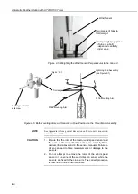
Assemble the Wind Monitor using a tri-clamp connector at the end of the 017E.
6.
Check that the Wind Monitor rotates freely and is perpendicular to the ground,
and fully tighten the Allen screw in the tri-clamp.
7.
Generally align the Wind Monitor to
true
North following the instructions
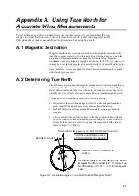
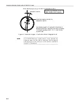
given for the 011E arm above, and in Appendix A.
2.3.4 018E Arm
— Wind Monitor and Pyranometer
This arm is a combination of the 016E and 017E and is assembled in the same way
as described for those arms, starting with the pyranometer. The 018E arm should
be fitted, together with the pyranometer, before the tower top section is attached to
the main tower structure, as discussed in Section 2.3.1, above. Ensure that the
pyranometer end of the arm points South. After fitting and levelling the
pyranometer, carefully attach the top tower section to the main tower structure.
Attach the Wind Monitor to the arm with the tower fully assembled but lying on
the ground. Set the Wind Monitor to true north as discussed above.
2.4 Fitting Optional Guy Wires to Tower Top Section
If you will be fitting the optional guying kit, you will need to attach the guy wires
to the tower before it is raised to its working position as follows:
1.
Cut the guy wire into three pieces – the lengths may differ, depending on your
site layout and slope, so ensure that you know the lengths before cutting.
2.
Attach the guy wires to the top tower section, taking each guy wire in turn
around the structure and fitting it securely using
three
U-bolts for each wire,
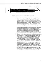
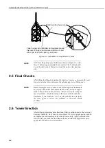
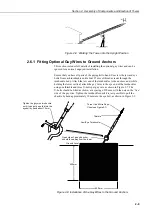
spaced as shown in Figure 2-7, below. Note the position of the ‘standing’ side
of the guy wire.

