Automatic Weather Station with UT20/UT30 Tower
2-8
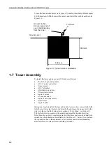
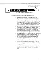
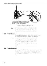
Figure 2-7 Installation of Guy Wires to Tower
All U-bolt Rope Clips must be fitted as shown in Figure 2-7, with
three U-bolts at approximately 20 mm centres. The U-bolts should
be on the short side of the guy wire and the nuts on the standing
side.
2.5 Final Checks
After fitting, levelling and orienting the high-level sensors as discussed, the next
step is to raise the tower and secure the optional guy wires, if being used.
Before raising the tower, double-check all the high-level instruments
and wiring. Ensure that the instrumentation wiring is long enough to
reach to the position of the enclosure. Always allow extra wiring for
ease of assembly. Attach the wiring to the tower with the cable ties.
Remember, if you make an error, you will probably have to lower
the tower again to correct any problems, so check all details
carefully.
2.6 Tower Erection
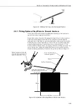
After all the appropriate sensors have been fitted, as outlined above, the tower can
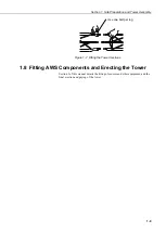
be raised. Carefully ‘walk’ the tower (see Figure 2-8) to its upright position and fit
and tighten the two remaining bolts in the base assembly. Again, ensure that the
sensor wiring can reach the site of the enclosure, and that the high level sensors
appear to be in their correct orientations.
NOTE
NOTE
Take the guy wire (thimbles not required) around
the tower structure and secure with three U-bolt
wire clips, at 20 mm spacing, as shown
Standing side of guy wire

