Automatic Weather Station with UT20/UT30 Tower
2-12
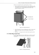
Attach the solar panel to the tower and, for northern hemisphere applications,
orient it to face due south. For short-term applications the panel should be angled
approximately perpendicular to the solar angle at mid-day. For longer term
unattended applications such as a 12-month period, the solar panel should be
angled to obtain best performance during the winter months. This ‘optimum tilt
angle’ is equivalent to the latitude plus 15 degrees, facing permanently due south.
Ensure that the solar panel will not be cast into shadow at any time by other
equipment mounted on the tower.
2.8 Connections
2.8.1 Power Supply Connections
With the PS12E-LA / PS512-M Power Supplies
Route the cable from the solar panel (where fitted) into the enclosure via the cable
gland or connector (if ordered). Connect it to the charger circuit of the power
supply (see power supply manual).
With External Battery
Please refer to the solar panel manual for full details. Route the power cable from
the external battery into the datalogger enclosure and connect it directly to the
datalogger.
When connecting an SOP18 or a solar panel supplied with a
separate regulator, make sure you observe the correct polarity
when connecting to the battery. Incorrect connection can
destroy the regulator.
2.8.2 Final Connections
1. Secure all grounding wire and sensor cables to the tower with cable ties.
2. Fit the sensor plugs into the sockets on the base of the enclosure following the
connection diagram supplied with each station.
3. Coil up any excess cable and strap it to the tower.
It is essential to secure excess cable to the tower as
unsecured lengths of cable can blow around in the wind
causing the wires to break inside, sometimes without any
external signs of damage.
4. Make additional connections to and from the datalogger through the large
cable gland; any unused plugs or sockets should be sealed off using the
sealing caps. Tighten the cable gland and check that it seals properly.
CAUTION
CAUTION

