Section 18. Installation
18-2
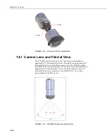
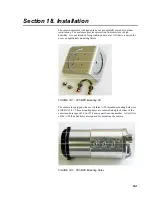
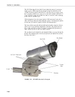
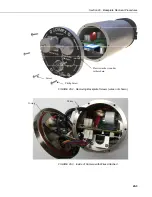
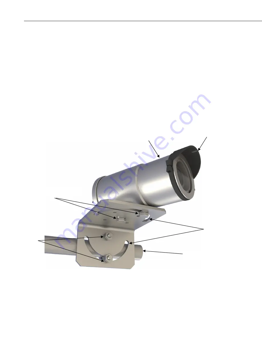
The 18549 Mounting Kit is available for mounting the camera to a crossarm,
tripod, or pole. When using this mounting kit, align the outer holes of the
CC5MPX with the center hole and the 180° slot of the mount. Loosely secure
the two together with the two ¼-20 x 0.5 in. Hex bolts included with the kit. It
is now possible to mount the CC5MPX to either a crossarm or other mounting
surface with the included u-bolt.
With the hardware loose, the camera and the 18549 mount can be pivoted to
allow a full range of motion when aiming the camera. The hardware should be
secured once the camera is properly aimed at the intended target.
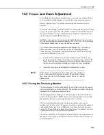
The focus of the camera should be checked and adjusted as required. Refer to
Section 14.2, Focus and Zoom Adjustment for details. Be sure that the lens
tube is fully seated, the sun shroud is properly orientated after the camera is
aimed, and any protective caps are properly secured.
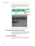
The sun shroud can be adjusted by loosening the Philips screws and turning the
shroud. When tightening the screws back up do not over tighten the screws as
the shroud may crack.
FIGURE 18-3. CC5MPX Mounted to Crossarm
¼-20 x 0.5” Hex bolts
Sun Shroud
Lens Tube
U-bolt
Curved
Slots
Crossarm
Summary of Contents for CC5MPX 6HULHV
Page 2: ......
Page 10: ...CC5MPX Table of Contents vi ...
Page 12: ...Section 1 Introduction 1 2 ...
Page 22: ...Section 3 Getting Started 3 8 FIGURE 3 7 CC5MPX Device Configuration Utility Settings Editor ...
Page 28: ...Section 4 Cables Wiring 4 6 ...
Page 36: ...Section 6 Camera Configuration 6 2 ...
Page 72: ...Section 7 Camera Operation Using Web Browser Interface 7 36 FIGURE 7 31 Motion Detection Page ...
Page 84: ...Section 10 RS 485 Communications 10 2 ...
Page 86: ...Section 11 PakBus Communications 11 2 ...
Page 88: ...Section 12 Device Configuration Utility 12 2 FIGURE 12 2 Device Configuration Utility Screen ...
Page 90: ...Section 13 Image Quality 13 2 ...
Page 98: ...Section 15 Power Calculations and Timings 15 4 ...
Page 104: ...Section 17 Remote Image Retrieval 17 4 ...
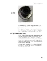
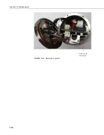
Page 110: ...Section 19 Maintenance 19 4 FIGURE 19 5 Desiccant Location Location of Desiccant ...
Page 116: ...Section 21 System Limitations 21 2 ...
Page 122: ...Section 23 Quick Notes 23 4 ...
Page 129: ......

