Section 20. Backplate Removal Procedures
20-2
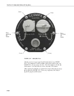
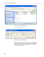
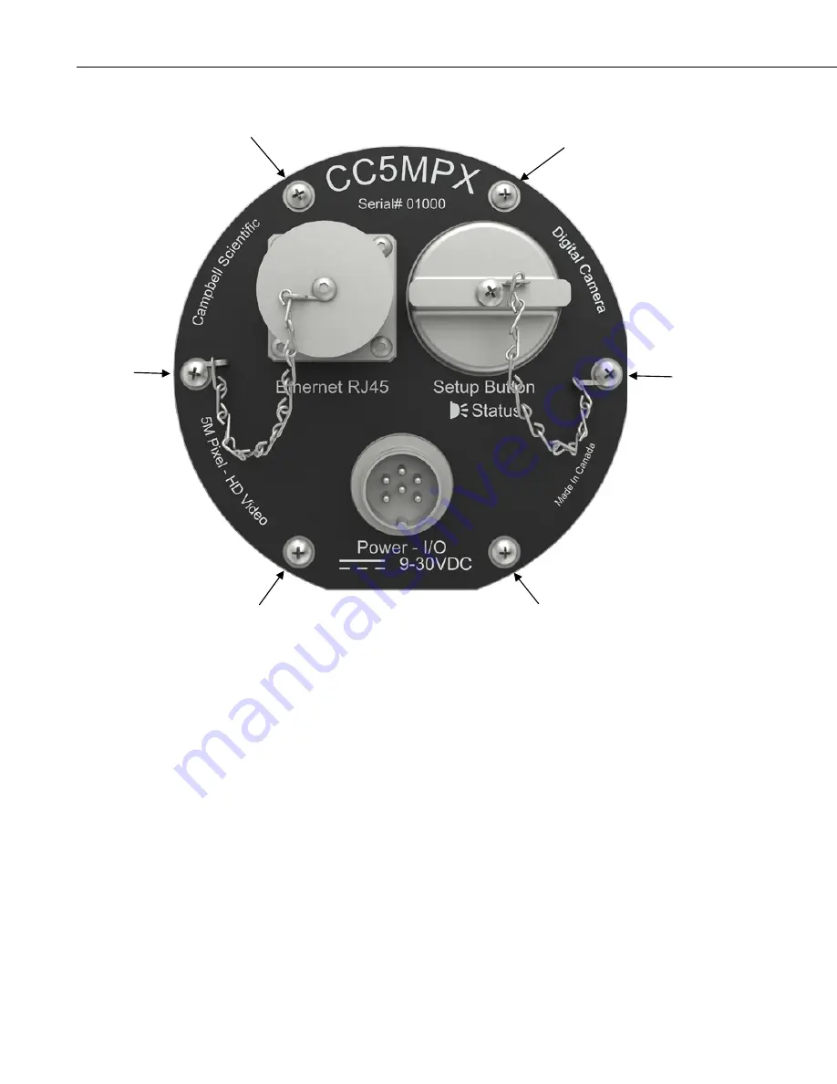
FIGURE 20-1. Backplate View
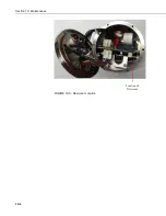
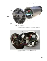
After the screws are removed, gently pull the backplate out (see FIGURE
20-2). The backplate will still be attached to the camera with the wires (see
FIGURE 20-3). Do not remove the wires. Pivot the backplate to the left side
of the camera. You will now have access to the inside of the camera.
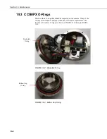
When replacing the backplate, ensure that the O-ring is still seated properly on
the backplate (see FIGURE 19-2). This is very important as the O-ring is
required to properly seal the camera.
Screw
Screw
Screw
with Chain
and
Washer
Screw
with Chain
and
Washer
Screw
Screw
Summary of Contents for CC5MPX 6HULHV
Page 2: ......
Page 10: ...CC5MPX Table of Contents vi ...
Page 12: ...Section 1 Introduction 1 2 ...
Page 22: ...Section 3 Getting Started 3 8 FIGURE 3 7 CC5MPX Device Configuration Utility Settings Editor ...
Page 28: ...Section 4 Cables Wiring 4 6 ...
Page 36: ...Section 6 Camera Configuration 6 2 ...
Page 72: ...Section 7 Camera Operation Using Web Browser Interface 7 36 FIGURE 7 31 Motion Detection Page ...
Page 84: ...Section 10 RS 485 Communications 10 2 ...
Page 86: ...Section 11 PakBus Communications 11 2 ...
Page 88: ...Section 12 Device Configuration Utility 12 2 FIGURE 12 2 Device Configuration Utility Screen ...
Page 90: ...Section 13 Image Quality 13 2 ...
Page 98: ...Section 15 Power Calculations and Timings 15 4 ...
Page 104: ...Section 17 Remote Image Retrieval 17 4 ...
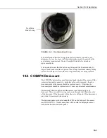
Page 110: ...Section 19 Maintenance 19 4 FIGURE 19 5 Desiccant Location Location of Desiccant ...
Page 116: ...Section 21 System Limitations 21 2 ...
Page 122: ...Section 23 Quick Notes 23 4 ...
Page 129: ......

