B-1
Appendix B. CC5MPXWD Window
Defroster Description
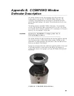
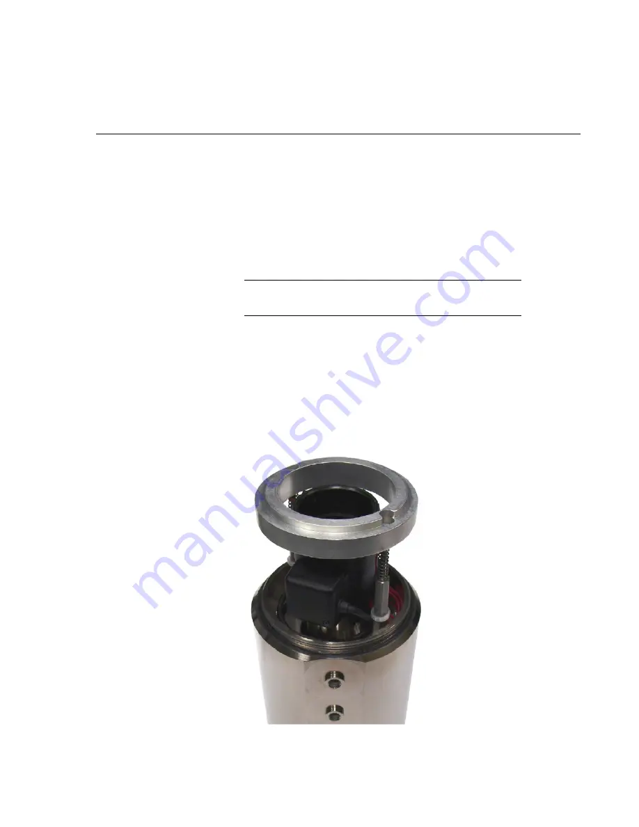
The window defroster consists of an aluminum ring with a resistive type
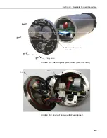
heating element (see Figure B-1 CC5MPXWD Window Defroster). The
camera can be programmed to turn on the power to the heater based on the
internal temperature reading of the camera. The on duration can also be set on
the camera.
The heating element is nominally 18 Ohms in resistance. The current draw
will vary with the allowable input voltage range of 9 to 16 VDC. The current
draw from the camera and heater combined is 1.2 A maximum at 16 Vdc and is
typically 1.0 A on a nominal 12 Vdc system.
Operating the CC5MPXWD at voltages greater than 16
Vdc may damage the camera.
The window defroster is useful in preventing and removing light frost and icing
from the camera window. With extreme icing or riming conditions and low
temperatures the window defroster may not be able to clear the window due to
the power constraints of the defroster.
Springs are used to press the window defroster against the window. It is normal
for the window defroster to leave marks on the window. These marks are
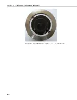
outside of the camera’s viewing angle (see Figure B-2 Window Defroster with
Lens Tube).
FIGURE B-1. CC5MPXWD Window Defroster
CAUTION
Summary of Contents for CC5MPX 6HULHV
Page 2: ......
Page 10: ...CC5MPX Table of Contents vi ...
Page 12: ...Section 1 Introduction 1 2 ...
Page 22: ...Section 3 Getting Started 3 8 FIGURE 3 7 CC5MPX Device Configuration Utility Settings Editor ...
Page 28: ...Section 4 Cables Wiring 4 6 ...
Page 36: ...Section 6 Camera Configuration 6 2 ...
Page 72: ...Section 7 Camera Operation Using Web Browser Interface 7 36 FIGURE 7 31 Motion Detection Page ...
Page 84: ...Section 10 RS 485 Communications 10 2 ...
Page 86: ...Section 11 PakBus Communications 11 2 ...
Page 88: ...Section 12 Device Configuration Utility 12 2 FIGURE 12 2 Device Configuration Utility Screen ...
Page 90: ...Section 13 Image Quality 13 2 ...
Page 98: ...Section 15 Power Calculations and Timings 15 4 ...
Page 104: ...Section 17 Remote Image Retrieval 17 4 ...
Page 110: ...Section 19 Maintenance 19 4 FIGURE 19 5 Desiccant Location Location of Desiccant ...
Page 116: ...Section 21 System Limitations 21 2 ...
Page 122: ...Section 23 Quick Notes 23 4 ...
Page 129: ......

