2-1
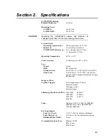
Section 2. Specifications
CC5MPXWD Heating
Element Resistance:
18
Ohms
Operating Power
CC5MPX:
9 to 30 Vdc
CC5MPXWD:
9 to 16 Vdc
Operating the CC5MPXWD camera and defroster at
voltages higher than 16 Vdc may damage the camera.
Current Drain
Operating (camera only):
250 mA maximum @ 12 Vdc
Quiescent:
≤
1 mA (off power mode)
CC5MPXWD defroster on:
1.2 A (maximum @ 16 Vdc);
1 A (typical @ 12 Vdc)
Operating Temperature:
-40
°
to +60
°
C
Clock Accuracy:
±2 minutes/year (-40
°
to 60
°
C)
Lens
Mount:
C-type
IRIS:
DC
compatible
Standard Lens:
4 to 12 mm, 27° to 80° field of view (FOV)
Zoom Lens:
10 to 40 mm, 9° to 35° FOV (ordered as a
special; contact Campbell Scientific for more
information)
Image or Video
Capture Triggers:
Two independent self timers
Motion
detection
Web page control
External trigger
Still Image
Resolution (JPEG):
2592x1944 640x352
1280x960
320x240
1280x720
320x176
640x480
Video:
Capable of 720P - 1280x720 (MPEG4),
640x480 (Live Video Only/MJPEG),
320x240 (MPEG4)
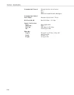
Ext. Input Signal
Logic Low Level:
<0.65 V (-20 Vdc absolute minimum)
Logic
High
Level:
>2.0 Vdc (+20 Vdc absolute maximum)
Minimum
Pulse
Width:
10
ms
Communication Interfaces:
Ethernet
10/100
RS-232
port
RS-485
port
CAUTION
Summary of Contents for CC5MPX 6HULHV
Page 2: ......
Page 10: ...CC5MPX Table of Contents vi ...
Page 12: ...Section 1 Introduction 1 2 ...
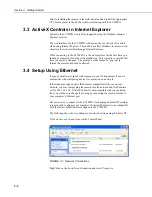
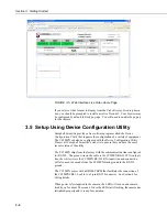
Page 22: ...Section 3 Getting Started 3 8 FIGURE 3 7 CC5MPX Device Configuration Utility Settings Editor ...
Page 28: ...Section 4 Cables Wiring 4 6 ...
Page 36: ...Section 6 Camera Configuration 6 2 ...
Page 72: ...Section 7 Camera Operation Using Web Browser Interface 7 36 FIGURE 7 31 Motion Detection Page ...
Page 84: ...Section 10 RS 485 Communications 10 2 ...
Page 86: ...Section 11 PakBus Communications 11 2 ...
Page 88: ...Section 12 Device Configuration Utility 12 2 FIGURE 12 2 Device Configuration Utility Screen ...
Page 90: ...Section 13 Image Quality 13 2 ...
Page 98: ...Section 15 Power Calculations and Timings 15 4 ...
Page 104: ...Section 17 Remote Image Retrieval 17 4 ...
Page 110: ...Section 19 Maintenance 19 4 FIGURE 19 5 Desiccant Location Location of Desiccant ...
Page 116: ...Section 21 System Limitations 21 2 ...
Page 122: ...Section 23 Quick Notes 23 4 ...
Page 129: ......

