4-1
Section 4. Cables/Wiring
4.1 Power and I/O Cable Connections
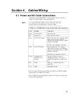
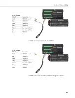
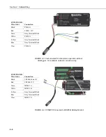
The wiring for the CC5MPXCBL1-L Power and I/O Cable is as shown in
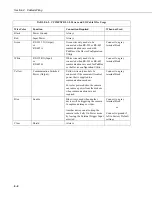
TABLE 4-1 and FIGURE 4-1 through FIGURE 4-4.
It is essential that the Ground cable be connected first when
wiring the camera to the datalogger or the power supply.
TABLE 4-1. CC5MPXCBL1-L Power and I/O Cable Color Connections
Color Function
Connection
Black
Power Ground
System Ground
Red
Input Power
Power Source 9-30 VDC
Green
RS-232 TX (Output)
RS-232 Input (Pin 2 of a computer (DTE)
DB-9 connector or even-numbered
control port of a TX/RX pair on a CR800,
CR1000, or CR3000)
RS-485A when configured to RS-485
White
RS-232 RX (Input)
RS-232 Output (Pin 3 of a computer
(DTE) DB-9 connector or odd-numbered
control port of a TX/RX pair on a CR800,
CR1000, or CR3000)
RS-485B when configured to RS-485
Yellow Communication
Switched Power
(Output)
This line is intended to power a
communication device. The camera
switches the Input Power voltage to this
line.
Blue
Enable
Wakes up or initiates image/video
acquisition.
Clear Shield
Shield/Earth
Ground
Refer to Section 8 Internal Jumpers if the current RS-232 or RS-485 interface
option needs to be changed in the camera.
Refer to TABLE 4-2 to help determine which wires will need to be connected
for your camera application.
NOTE
Summary of Contents for CC5MPX 6HULHV
Page 2: ......
Page 10: ...CC5MPX Table of Contents vi ...
Page 12: ...Section 1 Introduction 1 2 ...
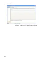
Page 22: ...Section 3 Getting Started 3 8 FIGURE 3 7 CC5MPX Device Configuration Utility Settings Editor ...
Page 28: ...Section 4 Cables Wiring 4 6 ...
Page 36: ...Section 6 Camera Configuration 6 2 ...
Page 72: ...Section 7 Camera Operation Using Web Browser Interface 7 36 FIGURE 7 31 Motion Detection Page ...
Page 84: ...Section 10 RS 485 Communications 10 2 ...
Page 86: ...Section 11 PakBus Communications 11 2 ...
Page 88: ...Section 12 Device Configuration Utility 12 2 FIGURE 12 2 Device Configuration Utility Screen ...
Page 90: ...Section 13 Image Quality 13 2 ...
Page 98: ...Section 15 Power Calculations and Timings 15 4 ...
Page 104: ...Section 17 Remote Image Retrieval 17 4 ...
Page 110: ...Section 19 Maintenance 19 4 FIGURE 19 5 Desiccant Location Location of Desiccant ...
Page 116: ...Section 21 System Limitations 21 2 ...
Page 122: ...Section 23 Quick Notes 23 4 ...
Page 129: ......

