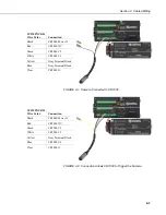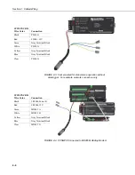
Section 4. Cables/Wiring
4-2
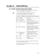
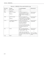
TABLE 4-2. CC5MPXCBL1-L Power and I/O Cable Wire Usage
Wire Color
Function
Connection Required
When not Used
Black Power
Ground
Always
Red Input
Power
Always
Green RS-232
TX
(Output)
or
RS-485 A
Green wire only needs to be
connected when RS-232 or RS-485
communications are used with
PakBus or the Device Configuration
Utility.
Connect to a gray
terminal block
White
RS-232 RX (Input)
or
RS-485 B
White wire only needs to be
connected when RS-232 or RS-485
communications are used for PakBus
or the Device configuration Utility.
Connect to a gray
terminal block
Yellow Communication
Switched
Power (Output)
Yellow wire only needs to be
connected if the camera will control
power that is supplied to a
communications modem.
For solar powered sites, the camera
can remove power from the modem
when communications are not
required.
Connect to a gray
terminal block
Blue
Enable
Blue wire is used when another
device will be triggering the camera
to capture an image or video.
Another device can also keep the
camera in the Fully On Power mode
by leaving the External Trigger Input
asserted.
Connect to a gray
terminal block
or
Connect to ground if
left in Factory Default
settings
Clear Shield
Always
Summary of Contents for CC5MPX 6HULHV
Page 2: ......
Page 10: ...CC5MPX Table of Contents vi ...
Page 12: ...Section 1 Introduction 1 2 ...
Page 22: ...Section 3 Getting Started 3 8 FIGURE 3 7 CC5MPX Device Configuration Utility Settings Editor ...
Page 28: ...Section 4 Cables Wiring 4 6 ...
Page 36: ...Section 6 Camera Configuration 6 2 ...
Page 72: ...Section 7 Camera Operation Using Web Browser Interface 7 36 FIGURE 7 31 Motion Detection Page ...
Page 84: ...Section 10 RS 485 Communications 10 2 ...
Page 86: ...Section 11 PakBus Communications 11 2 ...
Page 88: ...Section 12 Device Configuration Utility 12 2 FIGURE 12 2 Device Configuration Utility Screen ...
Page 90: ...Section 13 Image Quality 13 2 ...
Page 98: ...Section 15 Power Calculations and Timings 15 4 ...
Page 104: ...Section 17 Remote Image Retrieval 17 4 ...
Page 110: ...Section 19 Maintenance 19 4 FIGURE 19 5 Desiccant Location Location of Desiccant ...
Page 116: ...Section 21 System Limitations 21 2 ...
Page 122: ...Section 23 Quick Notes 23 4 ...
Page 129: ......


