Section 7. Camera Operation Using Web Browser Interface
7-5
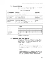
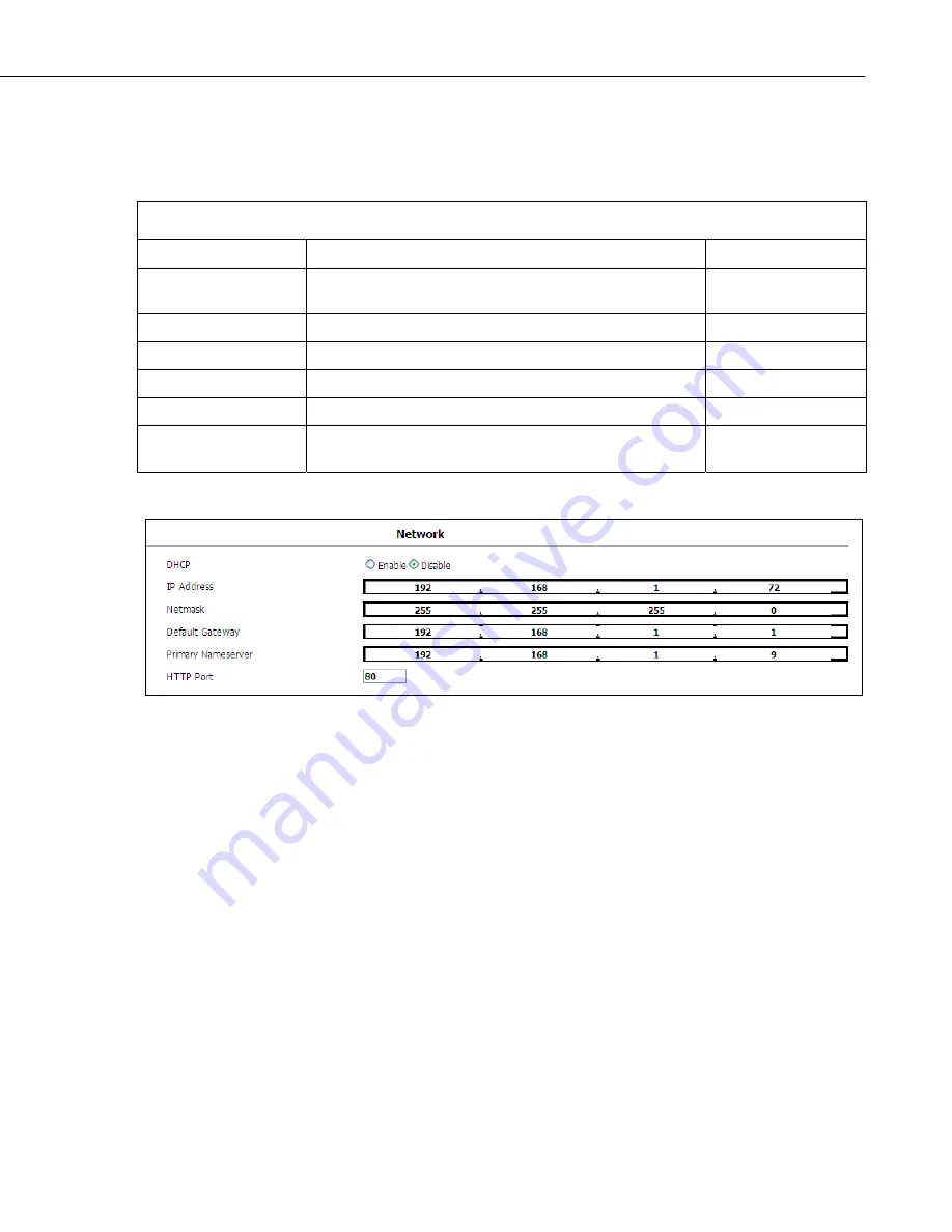
7.2.1 Network Settings
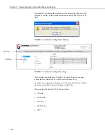
The most common network settings are displayed first in the Network sub tab.
These settings are summarized in the following table.
TABLE 7-1. Network Settings
Configuration Setting
Description
Default Value
DHCP
Enables DHCP operation of the network interface. Operates
as a Static IP address if Disabled.
Disabled
Network IP Address
Only set if DHCP is Disabled
192.168.1.90 (Static)
Network Mask
Only set if DHCP is Disabled
255.255.255.0
Default Gateway
Only set if DHCP is Disabled
192.168.1.1
Primary Name Server
Only set if DHCP is Disabled
192.168.1.1
HTTP Port
Alternate ports can be used for the http interface. Options
are 80 or values between 1025 and 65535.
80
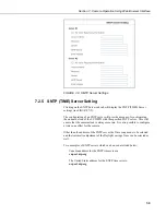
FIGURE 7-5. Network Settings
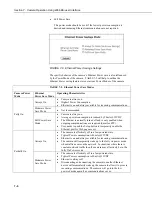
7.2.2 Ethernet Power Mode Settings
Clicking on the Power Mode sub tab will allow the user to edit the Ethernet
Power Mode setting. To reduce power consumption, the CC5MPX includes
the ability to control the power characteristics of the Ethernet port. Three
options are available (see FIGURE 7-6):
•
Always On
This power mode offers the maximum availability of the Ethernet port. If
the camera is in the Fully On power state or the Partially On power state
then the Ethernet port will always be on and available for communications.
•
Moderate
This power mode offers some power savings on the Ethernet port. This
mode is only recommended if the camera is being used in the Partially On
power mode. If the camera is in the Partially On power mode, then
incoming data packets will wake up the camera for communications.
Summary of Contents for CC5MPX 6HULHV
Page 2: ......
Page 10: ...CC5MPX Table of Contents vi ...
Page 12: ...Section 1 Introduction 1 2 ...
Page 22: ...Section 3 Getting Started 3 8 FIGURE 3 7 CC5MPX Device Configuration Utility Settings Editor ...
Page 28: ...Section 4 Cables Wiring 4 6 ...
Page 36: ...Section 6 Camera Configuration 6 2 ...
Page 72: ...Section 7 Camera Operation Using Web Browser Interface 7 36 FIGURE 7 31 Motion Detection Page ...
Page 84: ...Section 10 RS 485 Communications 10 2 ...
Page 86: ...Section 11 PakBus Communications 11 2 ...
Page 88: ...Section 12 Device Configuration Utility 12 2 FIGURE 12 2 Device Configuration Utility Screen ...
Page 90: ...Section 13 Image Quality 13 2 ...
Page 98: ...Section 15 Power Calculations and Timings 15 4 ...
Page 104: ...Section 17 Remote Image Retrieval 17 4 ...
Page 110: ...Section 19 Maintenance 19 4 FIGURE 19 5 Desiccant Location Location of Desiccant ...
Page 116: ...Section 21 System Limitations 21 2 ...
Page 122: ...Section 23 Quick Notes 23 4 ...
Page 129: ......

