v
7-4.
USB port on the CDM-VW300 .......................................................... 35
7-5.
Three-wire vibrating-wire sensor leads .............................................. 35
7-6.
Three-wire vibrating-wire sensor connection ..................................... 36
7-7.
Five-wire, vibrating-wire sensors leads .............................................. 36
7-8.
Five-wire vibrating-wire sensor connection ....................................... 37
7-9.
SC-CPI and CDM-VW300 CPI ports with RJ45 cable marked
with yellow tape.............................................................................. 38
7-10. CPI terminator installed ..................................................................... 38
7-11. Multiple analyzers on a CPI bus ........................................................ 39
7-12. Installing 12 Vdc transformer on the CDM-VW300 .......................... 40
7-13. Daisy-chaining 12 Vdc power input on the CDM-VW300 ................ 40
7-14. Earth ground connections ................................................................... 41
7-15. CR3000 and SC-CPI connections ...................................................... 42
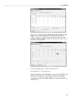
7-16. LoggerNet connect screens showing frequencies from
CDM-VW300 ................................................................................. 47
7-17. RTDAQ screens showing frequencies in
Public
table ....................... 48
7-18. Dynamic Vibrating-Wire Tool Box Fault Indicators ......................... 49
A-1. Timing of dynamic vibrating-wire measurements .......................... A-2
B-1.
Connection to the SC-CPI in DevConfig ......................................... B-2
C-1.
CPI pin assignments ......................................................................... C-2
C-2.
Long cable lengths of a distributed CPI bus ..................................... C-4
D-1. Geokon Calibration Report of a Sensor without a Thermistor ........ D-2
F-1.
Temperature measurement error at three temperatures as a
function of lead length. Wire is 22 AWG with 16 ohms per
1000 feet. ...................................................................................... F-2
F-2.
Temperature measurement error on a 1000 foot lead. Wire is
22 AWG with 16 ohms per 1000 feet. .......................................... F-3
F-3.
Temperature measurement error on a 3000 foot lead. Wire is
22 AWG with 16 ohms per 1000 feet. .......................................... F-3
F-4.
Temperature measurement error on a 5000 foot Lead. Wire is
22 AWG with 16 ohms per 1000 feet. .......................................... F-4
Tables
5-1.
CDM-VW300 / Datalogger Compatibility ........................................... 7
5-2.
CDM-VW300/305 Sensor Resonant Frequency Range (Hz) ............... 8
5-3.
CDM-VW300/305 Effective Frequency Measurement Resolution
4
.... 8
6-1.
CDM-VW300 Status LED States ....................................................... 15
6-2.
DVWTool and CRBasic Settings ....................................................... 17
7-1.
Summary of CDM-VW300 Configuration Settings ........................... 30
7-2.
Relationship of Sample Rate and Sensor Frequency .......................... 34
7-3.
Number of Analyzers and Channels Supported by a Datalogger
Writing to CF Card ......................................................................... 42
7-4.
CDM-VW300 Scan Rate / Datalogger Scan() Interval Pairings ........ 44
7-5.
CDM-VW300 Channel-Status LED States ........................................ 46
8-1.
Scan Rate and Boundary Resolution .................................................. 53
8-2.
Diagnostic Code Ranges .................................................................... 55
C-1.
Maximum Potential Speed as a Function of Distance
1
..................... C-2
Summary of Contents for CDM-VW300 Series
Page 2: ......
Page 4: ......
Page 6: ......
Page 12: ......
Page 59: ...User Manual 47 Figure 7 16 LoggerNet connect screens showing frequencies from CDM VW300 ...
Page 70: ...CDM VW300 Series Dynamic Vibrating Wire Analyzers 58 ...
Page 76: ...Appendix B SC CPI Datalogger to CPI Interface B 4 ...
Page 80: ...Appendix C CDM Devices and CPI Bus C 4 Figure C 2 Long cable lengths of a distributed CPI bus ...
Page 86: ...Appendix E Calculating Measurement Error E 4 ...
Page 116: ...Appendix G CRBasic Program Library G 26 ...


