CS-GSM/GPRS Digital Transceiver Kits (including the COM110A modem)
16
program stops running and the control port the yellow power control wire is
connected to is not driven.
Table 1 COM110A modem Power Supply Connections via a PSW12 switch
COM110A modem Cable Colour
Connection
Red (positive supply)
+ 12V
Black (negative supply)
G
Yellow (power control)
Control Port (or +12V for testing)
White (Failsafe function)
5V (normally)
N.B. These colours and connections only apply to the cable supplied by Campbell Scientific Ltd.
In the case of CR10X dataloggers, only the power switch in wiring
panels fitted with
green terminal blocks
is suitable.
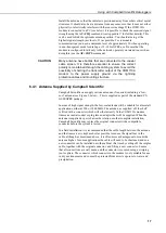
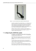
6.4 Selecting and Connecting an Antenna
When selecting an antenna, please note the following points:
Make sure the antenna used covers the frequency you intend to use the
COM110A modem on, i.e. does the antenna cover 900 or 1800 MHz, or both
(dual band).
Low cost,
¼
- or
½
-wave antennae are adequate for most applications where
signal coverage is good. It is important to realise that most low cost antennae
designed for vehicle mounting require a flat, metal sheet to form a ground
plane at the base of the antenna to achieve the specified gain figure and to
ensure proper impedance matching. As an approximate rule the ground plane
should have a radius equal to or greater than the height of the radiator.
Slightly higher priced co-linear, ‘marine’-grade antennae do not require such a
ground plane and can be more easily pole or cross-arm mounted.
In areas of poor signal coverage a directional, high-gain ‘Yagi’ antenna can be
considered, but this requires knowledge of where the cell base stations are
situated in order to enable proper alignment.
Raising the antenna is often the most effective way of getting better signal
reception. However, if long cables are required to achieve this, use low-loss
extension cables that do not have the significant signal loss of low cost cables.
Long cables are a particular problem when operating at 1800MHz.
Like most cellular-based systems, the COM110A modem varies its transmitter
power to ensure good communications with the remote cell station. Using a
cheaper, low-gain, antenna may result in a significant increase in power
consumption in areas of poor signal coverage.
If the antenna is placed near the top of a mast or has long antenna cables it may
be vulnerable to lightning damage. If lightning is common at the installation
site, additional lightning protection may be required to protect the COM110A
modem – please contact Campbell Scientific for further advice.
Using an antenna that is installed incorrectly, or with faulty wiring,
can lead to premature failure of the transmitter output of the
COM110A.
NOTE
CAUTION
Summary of Contents for COM110A
Page 2: ......
Page 4: ......
Page 6: ......
Page 10: ......
Page 48: ...CS GSM GPRS Digital Transceiver Kits including the COM110A modem 38...
Page 54: ......
Page 60: ......
Page 66: ......
Page 68: ...CS GSM GPRS Digital Transceiver Kits including the COM110A modem D 2...
Page 72: ......
Page 75: ......


